Description
1. Overview
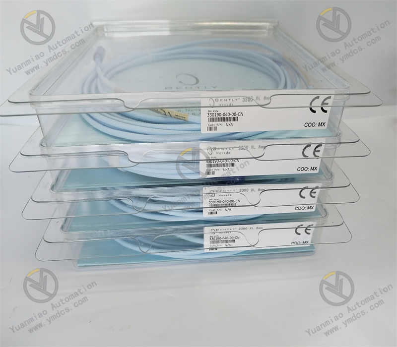
Bently Nevada 330190‑040‑00‑CN is a high‑precision piezoelectric accelerometer of the 3300 XL series by Baker Hughes Bently Nevada. It is a dedicated high‑frequency vibration‑sensing unit for condition‑monitoring of high‑speed rotating machinery. Designed for housing high‑frequency vibration and shock‑vibration measurement on critical rotating equipment such as steam turbines, compressors, fans, pumps and motors. This is a China‑standardized variant, fully compatible with Bently Nevada 3500 and 1900 monitoring systems. It works with proximitors and monitor modules for precise vibration‑signal acquisition, serving as a core sensing device for bearing‑fault, structural‑resonance and high‑frequency‑shock‑hazard monitoring of large‑scale industrial units.
The 330190 series features a hermetically‑sealed integrated stainless‑steel construction. Adopting piezoelectric‑ceramic sensing principle for non‑contact high‑response dynamic vibration acquisition, it delivers wide bandwidth, fast response, high linearity, low temperature drift and strong shock resistance. Unlike eddy‑current probes for displacement measurement, this unit focuses on high‑frequency acceleration measurement. It accurately captures latent faults that low‑frequency displacement probes cannot detect, such as rolling‑element wear, micro‑cracks, high‑frequency structural resonance and local impacts. Deployed in harsh industrial sites across thermal‑power, chemical, oil‑gas and metallurgical industries. Typical applications include refined unit condition‑monitoring, legacy‑point upgrade, special‑purpose high‑frequency‑fault monitoring and predictive‑maintenance retrofits.
2. Functions and Features
2.1 Core Functions
High‑precision High‑frequency Acceleration Vibration Monitoring: Dedicated acquisition of housing high‑frequency vibration and shock‑vibration signals. It identifies subtle high‑frequency vibration changes of rotating machinery and compensates blind spots of displacement probes for high‑frequency bearing faults. It covers fault‑monitoring requirements for bearing wear, structural resonance, local impact and component fatigue.
Wide‑band Full‑range Signal Acquisition: Standard industrial wide‑frequency response captures full‑band vibration signals without signal truncation or frequency distortion. It guarantees data integrity for fault spectrum analysis, vibration‑trend evaluation and precise condition diagnosis.
Standardized System Compatibility: Natively compatible with Bently Nevada 3500 rack‑mount monitoring systems, 1900 standalone monitor modules and mainstream third‑party vibration‑acquisition systems. Plug‑and‑play without extra signal conversion for new‑and‑old‑system retrofits and capacity expansion.
High‑dynamic Shock‑response Detection: Excellent shock‑withstand and transient‑response capability captures instantaneous high‑frequency shock vibration during unit start‑up / shutdown, load fluctuation and component jamming for early warning of sudden mechanical hazards.
Stable Analog Signal Output: Built‑in precision signal‑conditioning circuitry provides high‑linearity, low‑noise and stable analog sensor signals for long‑term continuous output. It supplies clean raw data for system calculation, trend logging, fault alarming and spectrum analysis.
24/7 All‑condition Continuous Monitoring: Designed for 7×24‑hour continuous industrial operation. It withstands cyclic temperature variation, dust, oil contamination and electromagnetic interference for long‑term reliable online condition‑monitoring of machinery units.
2.2 Product Characteristics
Superior Measurement Accuracy and Resolution: High‑performance piezoelectric‑ceramic sensing chip delivers fast dynamic response and ultra‑high resolution to capture micro‑level vibration variations. It meets requirements for precise condition‑monitoring and early latent‑fault diagnosis of industrial machinery.
Extra‑wide Operating Frequency Band: Optimized for high‑frequency vibration measurement. Its bandwidth covers key bearing‑fault frequency ranges to detect incipient bearing wear and micro‑structural defects invisible to conventional low‑frequency monitoring.
Exceptional Shock Resistance: Industrial‑grade reinforced construction offers outstanding mechanical‑shock and vibration‑fatigue resistance. It survives transient shocks during start‑stop and load changes with minimal zero‑point drift and performance degradation.
Hermetically‑sealed Robust Industrial Housing: One‑piece stainless‑steel hermetic enclosure provides dust‑proof, oil‑proof, moisture‑proof and corrosion‑proof performance. Well‑suited for harsh on‑site conditions with high temperature, heavy dust, oil pollution and strong electromagnetic interference for long service life.
Low‑drift High Long‑term Stability: Carefully‑selected industrial‑grade components achieve ultra‑low temperature drift. No parameter offset or zero‑point shift occurs under cyclic temperature conditions. Frequent recalibration is unnecessary and maintenance workload is reduced.
Broad Mounting Compatibility & Easy Maintenance: Standard industrial mounting design with universal fastening and simple cabling supports fast field replacement. Fault localisation is straightforward, ideal for large‑scale standardized retrofit, legacy‑sensor replacement and system expansion.
3. Specifications
| Item | Specifications |
|---|---|
| Model | 330190‑040‑00‑CN |
| Device Type | 3300 XL Series Piezoelectric Accelerometer |
| Brand & Manufacturer | Bently Nevada (Baker Hughes) |
| Detection Principle | Piezoelectric acceleration sensing principle |
| Measured Physical Quantities | Equipment housing high‑frequency vibration, shock acceleration |
| Nominal Sensitivity | 100 mV/g (factory industrial calibration) |
| Frequency Response Range | 10 Hz ~ 1 kHz (standard operating condition) |
| Measurement Accuracy | ±5% Full Scale |
| Resolution | 1 µm/s RMS |
| Signal‑to‑Noise Ratio | ≥70 dB |
| Overload Shock Resistance | 100 g continuous overload, 500 g transient shock |
| Compatible Systems | Bently Nevada 3500, 1900 series vibration‑monitoring systems and mainstream third‑party acquisition systems |
| Output Signal | Analog voltage sensor signal (for front‑end system acquisition) |
| Operating Temperature | ‑40 ℃ ~ +85 ℃ |
| Storage Temperature | ‑45 ℃ ~ +90 ℃ |
| Ambient Humidity | 5%‑95% RH, non‑condensing |
| Housing Material | Industrial‑grade stainless‑steel hermetically‑sealed structure |
| Operational Features | Wide‑band response, low temperature drift, low noise, high shock resistance, high linearity, long‑term drift‑free performance |
4. Operating Principle
The Bently Nevada 330190‑040‑00‑CN accelerometer operates on the piezoelectric‑effect dynamic‑sensing principle. Its high‑precision piezoelectric‑ceramic sensing element achieves accurate acquisition and linear conversion of housing high‑frequency‑vibration and transient‑shock signals, providing high‑frequency raw data for refined machinery‑fault diagnosis.
During equipment operation, high‑frequency vibration, micro‑deformation and transient shock from the machine housing are transmitted to the internal piezoelectric sensing unit. Subjected to mechanical stress, piezoelectric crystals generate charge polarization and convert mechanical acceleration into weak analog charge signals. Raw signals go through built‑in pre‑filtering, noise reduction and waveform‑shaping to suppress low‑frequency clutter, electromagnetic interference and spurious noise. Real high‑frequency vibration features are preserved to avoid signal distortion and frequency loss.
Processed sensor signals are transmitted via dedicated shielded cables to Bently Nevada proximitors and back‑end monitoring systems. The system performs AD sampling, spectrum analysis, RMS / peak‑value calculation and extracts key parameters such as bearing‑fault frequencies, structural‑resonance frequencies and shock‑characteristic frequencies. Real‑time high‑frequency‑vibration monitoring, trend analysis, over‑limit alarming and fault diagnosis are thus realised.
Benefiting from high‑stability piezoelectric material and hermetic sealing, the sensor tolerates on‑site condition fluctuation and mechanical shock while maintaining low drift and high‑linearity output. It features passive self‑diagnosis: sensor ageing, wiring anomaly or signal attenuation will cause regular offset in output amplitude and SNR, assisting maintenance personnel in early detection of measuring‑point faults and ensuring accuracy and continuity of the whole high‑frequency‑vibration monitoring chain.
5. Application Scenarios
High‑frequency Bearing‑fault Monitoring for Large‑scale Units: For bearing‑housing high‑frequency‑vibration monitoring of key primary equipment including steam turbines, centrifugal compressors, large‑size fans and high‑pressure pumps. It identifies early latent defects such as bearing pitting, wear, fatigue and rolling‑element failure and compensates blind spots of low‑frequency displacement monitoring.
Industrial‑equipment Structural‑resonance Monitoring: Collect high‑frequency vibration spectrum for housing, base and piping resonance issues. Accurately locate resonance frequencies and fault sources to supply data support for base reinforcement, piping modification and operating‑condition optimisation.
Transient‑shock Fault Prediction: Applied in unit start‑stop and variable‑load conditions to capture abnormal vibration from transient shock, jamming and friction. It predicts sudden mechanical faults in advance and prevents equipment damage and unplanned shutdown.
Refined Retrofit of Legacy Measuring Points: Replace conventional low‑frequency vibration points and degraded legacy sensors. It resolves weaknesses of old hardware including poor high‑frequency‑fault detection, data drift and low SNR to improve refinement level of machinery condition‑monitoring.
Long‑term Monitoring for Harsh Industrial Sites: Wide‑temperature operation, dust‑oil resistance, strong anti‑interference and high shock‑resistance enable stable deployment in thermal‑power, chemical and oil‑gas sites with high temperature, heavy dust, strong electromagnetic interference and severe condition fluctuation.
Data Support for Predictive Maintenance: Accumulate long‑term high‑frequency vibration trends and spectrum data to build equipment health models. It realises early fault warning, life prediction and targeted inspection for intelligent‑plant predictive‑maintenance upgrades.
6. Common Faults and Troubleshooting
6.1 Frozen readings with no fluctuation
Root Causes: Ageing / degraded piezoelectric sensing element; broken / loose sensor cable or oxidized terminals; mounting‑induced stress locking; abnormal parameters in back‑end acquisition channel.
Solutions: Inspect sensor mounting; release mounting stress and retighten fasteners. Check cable continuity and connector condition; clean and retighten terminals. Verify back‑end‑system configuration and restore standard acquisition mode. If readings remain static after external issues are eliminated, sensor hardware failure is confirmed; replace 330190‑040‑00‑CN.
6.2 High‑frequency data jitter, severe drift and poor SNR
Root Causes: Severe on‑site electromagnetic interference with improper shield‑grounding; loose sensor mounting causing parasitic resonance; damaged cable with failed shielding; performance degradation and increased noise after long‑term service.
Solutions: Implement single‑end shield grounding; route cables away from power circuits, variable‑frequency drives and high‑voltage loops. Retighten sensor to eliminate parasitic vibration. Inspect and replace damaged cables. Optimise field grounding and cabling to suppress EMI. Replace sensor if anomalies persist.
6.3 No high‑frequency features; flat monitoring spectrum
Root Causes: Damaged high‑frequency sensing element with failed frequency response; excessive signal attenuation in transmission lines; over‑aggressive filtering parameters in back‑end system masking valid high‑frequency signals; improper measuring‑point location.
Solutions: Verify sensor mounting position and relocate to effective vibration‑acquisition area. Optimise back‑end‑system filter and sampling‑frequency settings to restore high‑frequency acquisition. Inspect signal attenuation and rectify transmission loops. Replace sensor if no high‑frequency content appears despite correct parameters and wiring.
6.4 Low‑amplitude readings and insufficient measurement accuracy
Root Causes: Sensitivity degradation due to long‑term high‑temperature exposure; piezoelectric‑element fatigue; poor vibration transmission caused by oil / rust on mounting interface; excessive contact resistance in wiring.
Solutions: Clean mounting interface to remove oil and rust and ensure tight contact. Retighten terminals to reduce contact resistance. Calibrate sensor sensitivity and system acquisition coefficients. Replace sensor if accuracy cannot be recovered.
6.5 Intermittent signal dropout and sporadic data loss
Root Causes: Loose terminals from sustained equipment vibration; partial internal cable breakage due to bending fatigue; damp / oxidized connectors with degraded insulation; mechanical stress pulling sensor tail cable.
Solutions: Optimise cable routing to eliminate sharp bends and tensile stress. Clean and moisture‑proof connectors, then retighten connections. Secure cables and sensor tail against vibratory stress. Replace sensor together with matching cable if intermittent faults recur.
6.6 No sensor output; no measuring‑point signal in system
Root Causes: Complete cable breakage or incorrect wiring; burnt‑out piezoelectric unit and internal‑circuit damage; permanent hardware failure from sustained over‑temperature or over‑shock.
Solutions: Fully inspect cable continuity and pin‑out definitions and repair faulty wiring. Confirm no over‑temperature or over‑shock events on site. Replace genuine original sensor if no output is obtained under valid operating conditions.