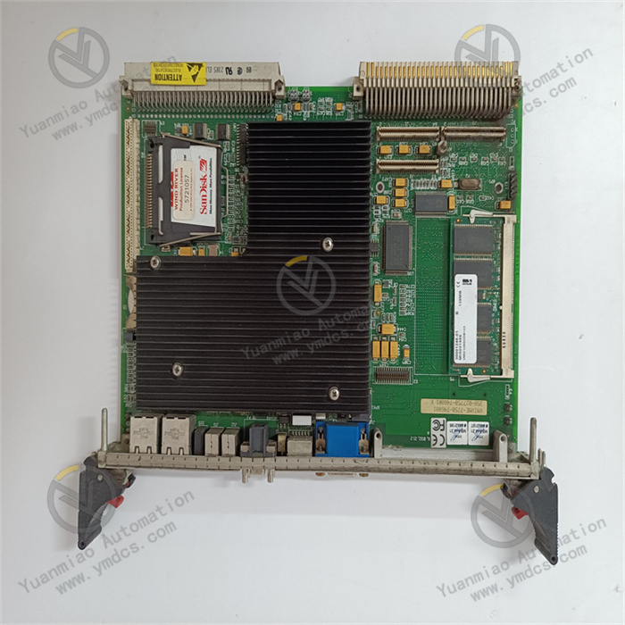
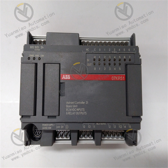
Description
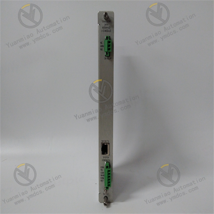
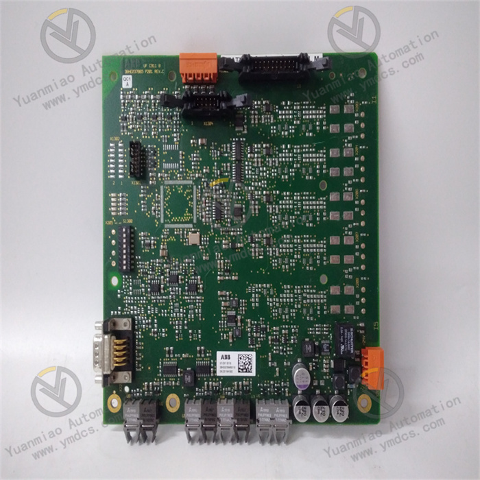
ABB CI856K01 3BSE026055R1
I. Basic Product Information
Series
It belongs to the communication interface module of the ABB AC 800M controller series, used in industrial automation systems to connect fieldbuses or third-party devices for data interaction and control.
It belongs to the communication interface module of the ABB AC 800M controller series, used in industrial automation systems to connect fieldbuses or third-party devices for data interaction and control.
Core Functions
- Multi-Protocol Communication: Supports mainstream industrial communication protocols (e.g., PROFIBUS DP, Modbus RTU/ASCII, Ethernet IP, PROFINET, etc., subject to model configuration).
- Data Interaction: Acts as a master or slave station to connect field devices such as sensors, actuators, and variable frequency drives, enabling real-time data transmission and control.
- System Integration: Configurable and diagnosable via ABB's Control Builder M software, supporting online programming and firmware upgrades.
Application Scenarios
- Industries: Power, chemical, metallurgy, pharmaceuticals, water treatment, food and beverage industries, etc.
- Scenarios: Suitable for automation systems requiring high-reliability communication, such as distributed control systems (DCS), PLC integration, and machine equipment networking.
II. Technical Parameters
| Parameter Category | Detailed Information |
|---|---|
| Communication Protocols | May support PROFIBUS DP V1/V2, Modbus RTU/ASCII, Ethernet IP, CANopen, etc. |
| Interface Types | - Physical interfaces: DB9 serial port, PROFIBUS bus interface, Ethernet interface (RJ45) - Electrical standards: RS-485/RS-232, Ethernet IEEE 802.3 |
| Data Transmission Rate | - PROFIBUS DP: Up to 12 Mbps - Modbus: Up to 115.2 kbps - Ethernet: 10/100 Mbps |
| Power Supply | DC 24 V (±10%), power consumption approx. 5–10 W |
| Operating Temperature | -40°C to +70°C (industrial-grade wide-temperature design) |
| Protection Level | IP20 (suitable for installation in control cabinets) |
| Certification Standards | CE, UL, CSA, ATEX (optional for explosion-proof scenarios), etc., compliant with industrial EMC standards |
| Redundancy Support | May support dual-bus redundancy or hot standby configuration (subject to system architecture) |

III. Product Features and Advantages
High Compatibility: Supports multiple protocols, adapting to devices from different manufacturers and reducing system integration complexity.
Reliability Design:
- Hardware watchdog and signal isolation (electrical isolation up to 2500 Vrms) for strong anti-interference capability.
- Supports redundancy configurations (e.g., dual-bus interfaces) to enhance system availability.
Convenient Maintenance:
- Status indicator lights (power, communication, fault) visually display operating status.
- Supports online diagnostics and firmware upgrades to minimize downtime.
High Performance: Built-in high-speed processor supports real-time data processing and protocol conversion with latency as low as milliseconds.
IV. Fault Diagnosis and Troubleshooting Methods
1. Preliminary Hardware Status Check
Indicator Diagnosis (quickly locate issues via LED status):
| Indicator | Normal Status | Abnormal Status and Possible Causes |
|---|---|---|
| PWR (Power) | Green, steady on | - Off: Power not connected, power supply cable fault, or module power damage - Flashing: Unstable voltage (e.g., excessive ripple) |
| RUN (Operation) | Green, periodic flashing | - Steady on/off: Module initialization failure, firmware damage, or hardware fault - Rapid flashing: Firmware upgrading (wait for completion) |
| COM (Communication) | Green, steady on or flashing | - Off: No communication signal (bus not activated or slave unresponsive) - Red: Communication link fault (e.g., cable break, address conflict) |
| ERR (Error) | Off | - Red, steady on: Module hardware fault (e.g., chip damage) - Flashing: Configuration error, communication timeout, or slave anomaly |
| BUS (Bus) | Green, steady on (master) | - Off: PROFIBUS bus not connected or terminal resistor not enabled - Red: Bus short circuit, grounding fault, or slave failure |
Operation Recommendations:
- Record abnormal indicator status, power off and reinsert the module, and check for good socket contact.
- If the fault persists, replace with an identical module to rule out hardware damage.
Physical Appearance Inspection:
- Check the module for physical damage such as burn marks, deformation, or socket oxidation.
- Verify that bus connectors (e.g., PROFIBUS connectors) are secure and terminal resistors are correctly set (enabled for master stations, disabled for slave stations).
- Ensure cable shields are well-grounded and kept away from strong electromagnetic sources (e.g., motors, frequency converters).
2. System Software Diagnosis
Read Diagnostic Logs and Error Codes:
View module status via ABB Control Builder M or control system software:
View module status via ABB Control Builder M or control system software:
- Common Error Codes:
BUS_ERROR: Bus communication failure (e.g., cable interruption, slave power loss).SLAVE_NOT_FOUND: Slave not detected (incorrect address or missing configuration).PARAMETER_MISMATCH: Configuration parameters mismatch with the slave (e.g., baud rate, parity).- Event Logs: Record fault occurrence time, type, and possible causes (e.g., timeout, checksum error).
Configuration Parameter Verification:
- Bus Address: Ensure the module's master address (e.g., PROFIBUS address 0–126) matches the software configuration and there are no address conflicts.
- Communication Parameters: Check that baud rate, data bits, stop bits, parity, etc., fully match the slave device.
- Slave Configuration: Confirm that slave GSD files (PROFIBUS) or device description files are correctly imported, and the number and models of slaves match the actual setup.
Firmware Version Check:
- Outdated firmware may cause compatibility issues. Check the version via software and upgrade to the latest official version.
- Upgrade Steps: Download firmware → power off the module → enter upgrade mode via software → follow prompts (avoid power interruptions).

3. Communication Fault Troubleshooting
Bus Signal Testing:
- Use a PROFIBUS diagnostic tool (e.g., Fluke DP tester) to measure bus voltage:
- No load (terminal resistor enabled): ~12 V DC.
- Under load (with slaves connected): ≥9 V DC. Abnormal voltage may indicate bus short circuits or slave faults.
- Test cable continuity with a multimeter and check shield grounding.
Segmented Isolation Method:
- Disconnect the bus in segments and reconnect slaves step by step while observing module status. If an error occurs after connecting a segment, the fault lies within that segment (e.g., faulty slave, damaged cable).
- Focus on checking power supply, address settings, and connector contact in the faulty segment.
Replacement Method Verification:
- Replace bus cables, connectors, or terminal resistors to rule out physical link issues.
- Replace the current slave with a known-good device to determine if the fault originates from the module or the slave.
4. Common Faults and Solutions
| Fault Phenomenon | Possible Causes | Solutions |
|---|---|---|
| Module without power (PWR off) | - Power module failure - Power supply cable open - Module power interface damage | - Check power output voltage - Replace cable or power module - Repair/replace module |
| Communication interrupted (COM off) | - Bus cable damage - Address conflict - Slave power loss - Electromagnetic interference | - Test cable continuity - Check slave addresses - Restore slave power - Optimize cabling and enhance shielding |
| Frequent error reports (ERR flashing) | - Configuration parameter errors - Firmware defects - Slave protocol incompatibility | - Recheck parameters - Upgrade firmware - Update slave GSD files or replace with compatible devices |
| Slave device unrecognized | - Incorrect slave configuration - Terminal resistor not enabled - Slave hardware failure | - Import correct GSD files - Enable terminal resistors - Replace slave devices |
| Module overheating (hot casing) | - Poor ventilation in the installation environment - Aging internal components | - Clean cooling vents, improve ventilation - Replace the module |
5. Maintenance and Preventive Measures
- Regular Inspections: Clean module cooling vents quarterly, tighten cable connectors, and check grounding.
- Redundancy Configuration: If supported, configure dual-bus or hot standby modules to reduce single-point failure risks.
- Document Management: Backup module configuration parameters, firmware versions, and slave description files for quick recovery.
- Training and Spare Parts: Train maintenance personnel on communication protocols and module diagnostics; stock common spare parts (e.g., modules, connectors).