Description
Technical Parameters
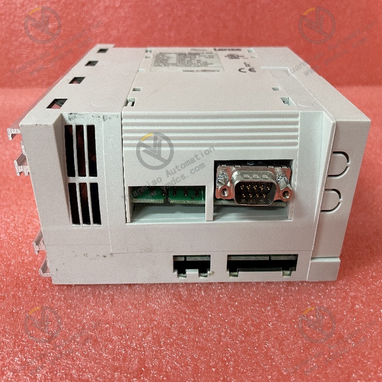
Electrical Parameters:
- Input voltage: 24VDC
- Inrush current at 400VAC: 7A
- DC bus capacitor: 470 µF
- Maximum current: 24A
- Output frequency: 600Hz
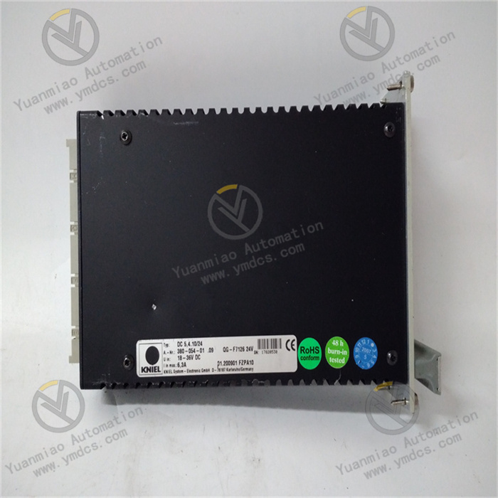
Physical Parameters:
- Dimensions: Width 70.5mm, Height 375mm, Depth 235.5mm
- Weight: 4.4 kg
- Protection class: IP20
Environmental Parameters:
- Operating temperature: 5 to 40 °C
- Installation altitude: Up to 2000 meters
Functional Features
High-Performance Control:
Equipped with advanced motion control algorithms and high-speed data processing capabilities, enabling precise position and speed control. Typically paired with high-resolution encoder feedback systems to provide accurate position feedback.
Multiple Control Modes:
Supports various control modes such as speed control, position control, and torque control, suitable for diverse applications including robot control, automated production lines, and printing machinery.
Multi-Axis Synchronization Control:
Some B&R servo drives feature multi-axis synchronization control, enabling precise coordinated motion between multiple servo motors—critical for applications requiring collaborative motor operation.
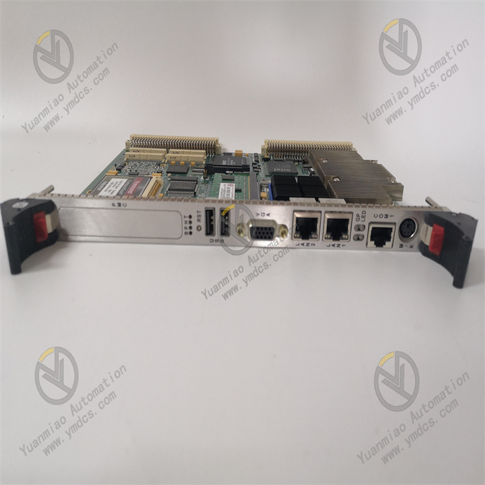
Rich Communication Interfaces:
Supports multiple communication interfaces and network protocols (e.g., EtherCAT, PROFINET, CANopen), facilitating data exchange and integrated control with other automation devices and systems.
Protection and Diagnosis Functions:
Includes overload protection, short-circuit protection, overheat protection, and diagnostic functions to monitor and identify fault conditions for rapid troubleshooting.
Application Scenarios
Robot Control:
Its multiple control modes and high-precision control capabilities meet the needs for precise position, speed, and torque control during robot movement, enabling complex motions and tasks.
Automated Production Lines:
Precisely controls motor movements in material handling, assembly, and other processes to ensure production accuracy and stability, while coordinating with other production line equipment.
Printing Machinery:
Accurately controls plate positioning, ink supply, and other parameters during printing to ensure quality and efficiency, achieving synchronized motion between multiple axes.
Fault Diagnosis and Troubleshooting Guide for B&R 8V1090.00-2 Drive
I. Basic Preparation for Fault Diagnosis
- Tools and Documentation
- Multimeter (for measuring voltage and current), oscilloscope (for detecting signal waveforms).
- Spare motors and cables (for replacement testing).
- B&R Automation Studio (requires corresponding version) for connecting to the drive to read real-time data, fault codes, and configure parameters.
- Serial debugging tools (e.g., PuTTY) or industrial bus configuration software (e.g., Ethernet POWERLINK tools) for communication fault troubleshooting.
- Software Tools:
- Hardware Tools:
- Initial Inspection Steps
- Measure the input power voltage (e.g., three-phase AC 200-240V or single-phase, confirmed by model) for stability, within the allowable fluctuation range (typically ±10%).
- Check power filters and circuit breakers to avoid false faults caused by power supply issues.
- Check for obvious damage to the drive casing (e.g., deformation, burn marks), and ensure the fan is not stuck or making unusual noises.
- Inspect terminal connections for looseness, oxidation, or damaged cables (focus on power cables, encoder cables, and bus cables).
- Visual Inspection:
- Power Supply Test:
II. Fault Code Analysis and Handling
B&R drives indicate faults via LED indicators or software error codes. Below are typical fault categories and troubleshooting procedures:
- Power-Related Faults
Fault Code/Issue Possible Causes Solutions F0001 Overvoltage - Excessive input voltage (e.g., >264V AC)
- Excessive regenerative braking energy- Check input power stability
- Add braking resistors or adjust braking parameters (e.g., extend deceleration time)
- Verify brake chopper activationF0002 Undervoltage - Insufficient input voltage (e.g., <170V AC)
- Loose power cable connections
- Blown fuse- Measure actual input voltage
- Tighten power terminals and replace damaged cables
- Inspect and replace fusesLED no display/abnormal flashing - Power not connected
- Internal power module failure
- Firmware corruption- Reconnect power connector
- Power cycle the drive; if ineffective, contact technical support to replace the power module
- Upgrade or restore firmware via Automation Studio - Motor and Encoder Faults
Fault Code/Issue Possible Causes Solutions F0010 Encoder Error - Encoder cable open/short circuit or interference
- Faulty encoder
- Incorrect motor identification parameters- Use an oscilloscope to check encoder signal waveforms (e.g., sinusoidal amplitude)
- Replace encoder cable (use shielded twisted-pair cable)
- Re-identify motor parameters (P2001-P2003)F0012 Motor Overheating - Motor overload
- Inadequate cooling (fan failure or high ambient temperature)
- Faulty encoder temperature sensor- Check load inertia and adjust acceleration/deceleration times
- Clean cooling vents and replace fans
- Measure temperature sensor resistance with a multimeter to diagnose faultsMotor vibration/unusual noise - Misaligned mechanical installation
- Abnormal encoder signals
- Unoptimized drive parameters (e.g., excessive current loop gain)- Re-calibrate mechanical alignment (coaxiality error ≤0.02mm)
- Troubleshoot encoder cable interference
- Adjust control loop parameters (e.g., reduce speed loop proportional gain P1001) - Communication and Bus Faults
Fault Code/Issue Possible Causes Solutions F0030 Bus Communication Interruption - Loose bus cable connections
- Missing terminator resistor
- Bus address conflict
- Incompatible drive firmware version- Check bus connectors (e.g., RJ45, DB9) and install terminator resistors (typically 120Ω)
- Ensure unique bus addresses for all nodes
- Upgrade drive firmware to a compatible version via Automation StudioDrive not recognized - Drive not powered
- Incorrect bus protocol configuration (e.g., baud rate, message format)
- Missing controller-side driver- Ensure drive power is active
- Select the correct bus type (e.g., Ethernet POWERLINK) in Automation Studio
- Install the appropriate driver for the controller - Overload and Short Circuit Faults
Fault Code/Issue Possible Causes Solutions F0004 Motor Overload - Load exceeds motor rated torque
- Mechanical blockage
- Improper current loop parameters (e.g., too small integral time)- Measure actual torque with a power meter and confirm against rated values (refer to the manual for torque range of 8V1090-compatible motors)
- Manually rotate the load to check mechanical smoothness
- Increase current loop integral time (P1004)F0005 Power Module Short Circuit - Phase-to-phase short in motor cables
- Internal power module damage
- Motor insulation breakdown- Disconnect motor cables and measure motor winding insulation resistance with a megohmmeter (≥1MΩ)
- Test with a spare motor; if the fault persists, the drive’s power module may need factory repair

III. Advanced Diagnostic Techniques
- Data Monitoring and Waveform Analysis
- Current (Iq): Should be stable during normal operation; significant fluctuations indicate overload.
- Speed (n): Compare with command values to assess speed loop tracking performance.
- Encoder Position (Pos): Check for jumps or lag to troubleshoot encoder signal stability.
- Real-Time Parameter Monitoring:
Use the oscilloscope function or online monitoring window in Automation Studio to observe key parameters: - Waveform Recording:
Capture voltage and current waveforms during faults to analyze for spike interference or harmonic 超标 (possibly caused by frequency converters, welding machines, etc.). Add output reactors or filters if necessary. - Replacement Method and Segmented Testing
- Replace Suspicious Components:
Swap with a known-good drive of the same model to determine if the fault lies with the drive itself. Replace peripheral components (motors, cables, encoders) to locate the fault point. - Segmented Isolation Testing:
Disconnect the load and run the drive with the motor idling to check for faults (to distinguish between mechanical and electrical issues). Gradually reconnect peripheral devices (sensors, actuators) to identify interference from third-party equipment. - Firmware Upgrade and Parameter Reset
- Firmware Upgrade:
For rare fault codes (e.g., custom codes above F0050), which may indicate firmware bugs, connect to the drive via Automation Studio and install the latest official firmware. - Parameter Reset:
If parameter configuration is corrupted (e.g., accidental changes to control mode or encoder type), perform a factory reset (via panel buttons or software, following manual procedures), then reconfigure motor parameters and control modes.
IV. Preventive Maintenance Recommendations
- Regular Inspections:
Clean drive cooling vents quarterly to prevent dust accumulation and poor heat dissipation. Tighten terminal connections and inspect cable aging annually. - Parameter Backup:
Export drive parameter files (.xml format) in Automation Studio and store them securely for quick configuration recovery after faults. - Environmental Optimization:
Ensure the installation environment temperature is 0°C~55°C and humidity ≤90% (no condensation). Keep power and signal cables at least 30cm apart from strong electromagnetic sources.