Description
Manufacturer : B&R
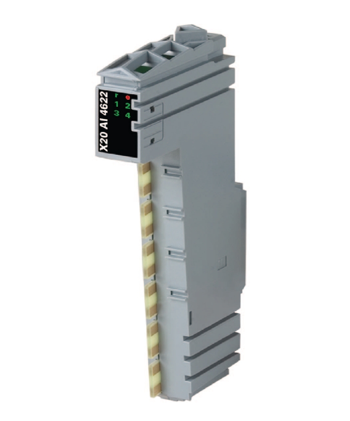
Product no : X20AI4622
Product type : Control systems
4 analog inputs
Either current or voltage signal possible
13-bit digital converter resolution
The module is equipped with 4 inputs with 13-bit (including sign) digital converter resolution. It is possible to select between the current and voltage signal using different
connection terminal points.
B&R ID code : 0x1BAA
Status indicators : I/O function per channel, operating state, module status
Diagnostics
Module run/error : Yes, using status LED and software
Inputs : Yes, using status LED and software
Channel type : Yes, using software
Power consumption
Bus : 0.01 W
Internal I/O : 1.1 W
Additional power dissipation caused by actuators (resistive) [W] : -
Certifications
CE : Yes
KC : Yes
UL : cULus E115267
Industrial control equipmentHazLoc : cCSAus 244665
Process control equipment
for hazardous locations
Class I, Division 2, Groups ABCD, T5ATEX : Zone 2, II 3G Ex nA nC IIA T5 Gc
IP20, Ta (see X20 user's manual)
FTZÚ 09 ATEX 0083XDNV GL : Temperature: B(0 - 55°C)
Humidity: B(up to 100%)
Vibration: B(4 g)
EMC: B(bridge and open deck)Input : ±10 V or 0 to 20 mA / 4 to 20 mA, via different terminal connections
Input type : Differential input
Digital converter resolution
Voltage : ±12-bit
Current : 12-bit
Conversion time : 400 µs for all inputs
Output format : INT
Output format
Voltage : INT 0x8001 - 0x7FFF / 1 LSB = 0x0008 = 2.441 mV
Current : INT 0x0000 - 0x7FFF / 1 LSB = 0x0008 = 4.883 µA
Input impedance in signal range
Voltage : 20 MO
Current : -
Load
Voltage : -
Current : <400 O
Input protection : Protection against wiring with supply voltage
Permissible input signal
Voltage : Max. ±30 V
Current : Max. ±50 mA
Output of digital value during overload : Configurable
Conversion procedure : SAR
Input filter : 3rd-order low pass / cutoff frequency 1 kHz
Max. error at 25°C
Voltage
Gain : 0.08%
Offset : 0.015%
Current
Gain : 0 to 20 mA = 0.08 % / 4 to 20 mA = 0.1 %
Offset : 0 to 20 mA = 0.03 % / 4 to 20 mA = 0.16 %
Max. gain drift
Voltage : 0.006 %/°C
Current : 0 to 20 mA = 0.009 %/°C
4 to 20 mA = 0.0113 %/°CMax. offset drift
Voltage : 0.002 %/°C
Current : 0 to 20 mA = 0.004 %/°C
4 to 20 mA = 0.005 %/°CCommon-mode rejection
DC : 70 dB
50 Hz : 70 dB
Common-mode range : ±12 V
Crosstalk between channels : <-70 dB
Nonlinearity
Voltage : <0.025%
Current : <0.05%
Isolation voltage between channel and bus : 500 Veff
Electrical isolation : Channel isolated from bus
Channel not isolated from channelMounting orientation
Horizontal : Yes
Vertical : Yes
Installation elevation above sea level
0 to 2000 m : No limitations
>2000 m : Reduction of ambient temperature by 0.5°C per 100 m
Degree of protection per EN 60529 : IP20
Temperature
Operation
Horizontal mounting orientation : -25 to 60°C
Vertical mounting orientation : -25 to 50°C
Derating : -
Storage : -40 to 85°C
Transport : -40 to 85°C
Relative humidity
Operation : 5 to 95%, non-condensing
Storage : 5 to 95%, non-condensing
Transport : 5 to 95%, non-condensing
Note : Order 1x X20TB12 terminal block separately
Order 1x X20BM11 bus module separatelySpacing : 12.5+0.2mm
Shipping Weight : 1 Kg
Features High-precision measurement: It can collect and convert analog input signals with high precision, and accurately measure various physical quantities such as voltage, current, temperature, and pressure, providing accurate data support for industrial control systems. Multi-channel input: It usually has multiple analog input channels, allowing multiple sensors or signal sources to be connected simultaneously, enabling synchronous monitoring and processing of multiple physical quantities, and improving the integration and efficiency of the system. Wide input range: It supports a wide range of input signals and can adapt to the output signals of different types of sensors. For example, it can accept various standard voltage signals (such as 0 - 10V, -10 - 10V, etc.) and current signals (such as 4 - 20mA, 0 - 20mA, etc.), enhancing the versatility and flexibility of the module. Strong anti-interference ability: It adopts advanced electromagnetic compatibility design and has good anti-interference performance. It can work stably in complex industrial electromagnetic environments, ensuring the accuracy and reliability of input signals and reducing the impact of external interference on measurement results.
Technical Parameters Number of input channels: Generally, it has multiple channels. Commonly, it may have 8 channels or 16 channels, etc., and the specific number depends on the product model. Input signal types: It supports multiple types of analog input signals, including voltage signals and current signals. For example, the voltage signal range can be 0 - 10V, -10 - 10V, 0 - 5V, etc.; the current signal range can be 4 - 20mA, 0 - 20mA, etc. Resolution: It usually has a high resolution, such as 12 bits, 14 bits, or 16 bits, etc., and can accurately convert analog signals into digital signals to meet application scenarios with different precision requirements. Sampling frequency: It has a certain sampling frequency and can quickly sample input signals according to actual application requirements. For example, the sampling frequency may be between several hundred Hz and several thousand Hz to ensure that signal changes can be captured in a timely manner. Operating voltage: Generally, it is 24V DC, meeting the requirements of industrial standard power supplies and allowing a certain voltage fluctuation range to adapt to different industrial field power supply conditions.

Common Faults and Solutions
No input signal in the channel
Fault phenomenon: After connecting the sensor, the input value of the corresponding channel remains zero or does not change.
Solution: First, check whether the sensor is working properly, which can be judged by measuring the output signal of the sensor. Check whether the connection line between the sensor and the module is correct and firm, and whether there are open circuits or short circuits. Check whether the channel configuration parameters of the module are correct and whether they match the output signal type and range of the sensor.
Inaccurate measurement value
Fault phenomenon: The analog data collected by the module does not match the actual physical quantity, and there is a large error.
Solution: Check the accuracy and calibration of the sensor to ensure that the sensor measures accurately. Confirm whether the range setting of the module is correct and whether it is consistent with the output range of the sensor. Check whether there is interference in the electromagnetic environment, and shielding measures or adjustment of the wiring method can be taken to reduce the impact of interference on the signal.
Module communication failure
Fault phenomenon: The module cannot communicate normally with the controller or other devices, resulting in the inability to transmit data or issue control commands.
Solution: Check whether the communication interface of the module is correctly connected and whether the communication cable is intact. Confirm whether the communication parameter settings, such as baud rate, data bits, stop bits, parity bits, etc., are consistent with other devices. Check whether network devices (such as switches, routers, etc.) are working properly and whether the network configuration is correct. If the module supports hot swapping, try to re-plug the module to see if the communication can be restored. If the problem still exists, refer to the user manual of the module, find the relevant error codes and solutions, or contact B&R's technical support staff for further fault troubleshooting and repair.