Description
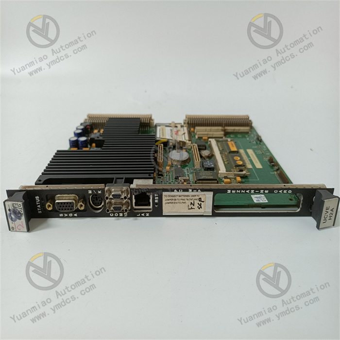
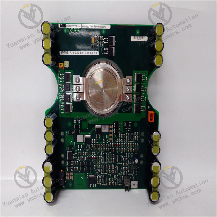
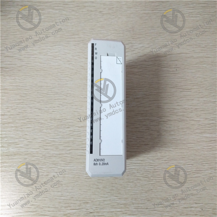
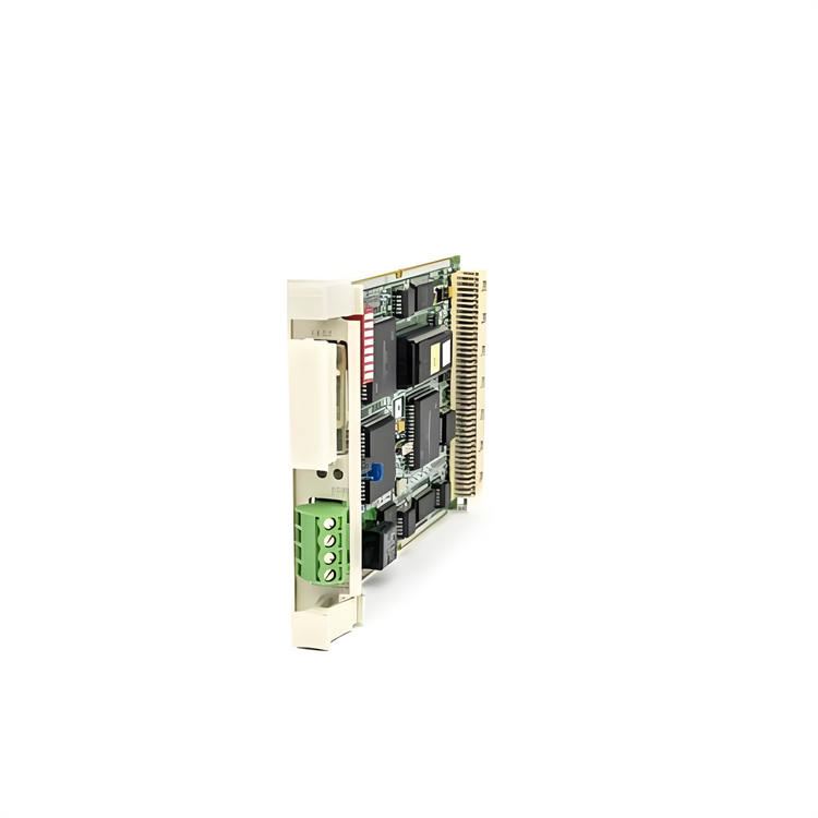
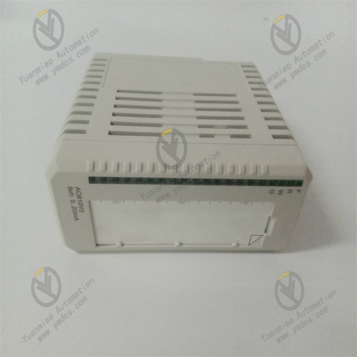
GE IC693ALG392
I. Overview
GE IC693ALG392 is an analog mixed output module belonging to the PACSystems RX3i/Series 90-30 product line, specifically designed for industrial automation control systems. Its core function is to convert digital signals from PLCs into high-precision analog signals, driving actuators (such as valves, frequency converters, and sensors) to implement process control. Compatible with the GE Proficy Machine Edition development platform and supporting hot-swap maintenance, this module is widely used in process control, equipment monitoring, and energy management scenarios across industries including chemical, petroleum, energy, water treatment, and manufacturing.
II. Key Features
Flexible Multi-Channel Configuration
- Equipped with 8 independent single-ended output channels, each configurable via software as voltage mode (0-10V unipolar / -10V~+10V bipolar) or current mode (0-20mA / 4-20mA) without hardware jumpers, adapting to diverse control requirements.
- Enhanced current mode supports 0mA open-circuit fault detection, meeting status monitoring needs in harsh industrial environments.
High Precision & Fast Response
- Resolution up to 15-16 bits (depending on output range), with a minimum step size of 0.3125mV for voltage signals and 0.5μA for current signals (4-20mA mode), ensuring precise signal output.
- Full-channel update rate of 8ms, single-channel sampling rate of 100 times/second, and response time <10ms, suitable for dynamic real-time control scenarios (e.g., motor speed regulation, temperature control).
- Output accuracy of ±0.1% of full scale (voltage mode) and ±0.2% of full scale (current mode), delivering excellent data stability.
Isolation & Safety Protection
- 250V AC continuous optoelectronic isolation design with independent channel-to-channel isolation, effectively preventing signal interference and crosstalk.
- Supports short-circuit and open-circuit fault detection, featuring high/low limit alarm functions for real-time output status feedback; strong electromagnetic interference (EMI) resistance, suitable for harsh industrial environments.
- Power failure retention function (FlashROM + lithium battery) ensures no data loss, enhancing system reliability.
Strong System Compatibility
- Compatible with GE PACSystems RX3i/RX7i and Series 90-30 platforms, enabling flexible combination with digital I/O and communication modules to build distributed control systems.
- Supports standard industrial protocols such as Modbus TCP and EtherNet/IP for data exchange with third-party devices; communicates with CPU modules via the backplane bus, simplifying wiring.
III. Technical Specifications
| Category | Detailed Specifications |
|---|---|
| Channel Configuration | 8 single-ended output channels, supporting voltage/current mode switching |
| Output Range | Voltage: 0-10V (unipolar), -10V~+10V (bipolar); Current: 0-20mA, 4-20mA |
| Accuracy Indices | Voltage: ±0.1% of full scale; Current: ±0.2% of full scale; Resolution: 15-16 bits (varies with output range) |
| Response Performance | Full-channel update rate: 8ms; Single-channel sampling rate: 100 times/second; Response time: <10ms |
| Power Supply Requirements | Backplane power: 5VDC/120mA; External power: 24VDC/65mA (supports 20-30VDC wide-voltage input) |
| Environmental Adaptability | Operating temperature: -20℃~60℃; Storage temperature: -40℃~70℃; Humidity: 5%-95% (non-condensing) |
| Physical Specifications | Dimensions: Approx. 115mm×100mm×25mm; Weight: Approx. 0.3kg; Mounting method: DIN rail/screw fixation |
| Power Consumption | Backplane 5V bus: 110mA; External 24V power supply: 315mA |
IV. Working Principle
The core working logic of the IC693ALG392 is the "accurate conversion and stable output of digital signals to analog signals," with the specific process as follows:
- Signal Reception: The module receives digital control commands (e.g., valve opening, motor speed setpoint) from the PLC CPU via the backplane bus. After being parsed by the module's internal logic circuit, the commands are transmitted to the signal conversion unit.
- Mode Configuration: Based on the channel mode (voltage/current, unipolar/bipolar) preconfigured via the Proficy Machine Edition software, the signal conversion rules (e.g., mapping relationship between digital quantities and 0-10V voltage) are determined.
D/A Conversion: A 16-bit high-precision digital-to-analog converter (DAC) converts digital signals into corresponding analog signals. During conversion, internal factory-calibrated circuits ensure accuracy, with a minimum step size of 0.3125mV for voltage signals and 0.5μA for current signals.
- Isolated Output: The converted analog signals are processed by the optoelectronic isolation unit to avoid backplane bus interference, then output to actuators (e.g., valve positioners, frequency converters) via independent channels. Meanwhile, the module real-time monitors the output signal status; if a short circuit, open circuit, or over-range condition is detected, it immediately triggers an alarm and feeds back to the CPU.
- Fault Feedback: Fault information (e.g., open circuit, short circuit) is transmitted back to the PLC via the backplane bus. Users can view alarm details through upper computer software to enable rapid troubleshooting.
V. Operation Guide
1. Installation Steps
Installation Environment
- Select a dry, well-ventilated area inside the control cabinet, avoiding high temperature, humidity, and dusty environments.
- The module must be fixed in a metal enclosure to enhance EMI resistance.
Physical Installation
- Adopt standard DIN rail mounting or fix to the mounting plate with screws.
- The module features a compact design (115mm×100mm×25mm); reserve heat dissipation space with a minimum distance of ≥5mm between adjacent modules.
Wiring Specifications
- Connect the external 24VDC power supply directly to the module terminal block, ensuring correct polarity (avoid reverse connection).
- Use AWG 14-22 gauge wires for output signal lines. Route voltage signal lines away from power lines to avoid parallel routing; use shielded and grounded wires for current signals to reduce interference.
- Follow the terminal definitions for channel wiring (refer to the module manual) to ensure correct connection of "Signal +" and "Signal -" and prevent short circuits.
2. Software Configuration (Based on GE Proficy Machine Edition)
Module Addition
- Open the software project, add the "IC693ALG392" module in the hardware configuration interface, and select the corresponding PLC platform (RX3i/Series 90-30).
Channel Configuration
- For each channel, set the output type (voltage/current), output range (e.g., 4-20mA, -10V~+10V), resolution (15/16 bits), and alarm thresholds (high/low limits).
Parameter Calibration
- No manual calibration is required (factory preset calibration values: 0.625μA for 0-20mA mode, 0.5μA for 4-20mA mode, 0.3125mV/count for voltage mode). If adjustment is needed, use the software calibration function for correction.
Download & Operation
- After configuration, download the project to the PLC CPU. The module automatically identifies the configuration parameters and starts working; monitor the output status of each channel via the software.
3. Operation & Maintenance
Status Monitoring
- View channel output values and alarm information (e.g., open circuit, short circuit) through the upper computer software. The module's Power/Run indicator is steady on during normal operation and the fault indicator flashes when an alarm occurs.
Hot-Swap Operation
- Supports hot-swap maintenance. Before replacing the module, disconnect the external power supply first, then remove the module to avoid damaging the backplane bus.
Regular Maintenance
- Inspect wiring terminals for looseness and module heat dissipation every 6 months.
- Calibrate the output accuracy annually to ensure stable performance.
- Prevent the module from contacting corrosive gases or liquids.
4. Common Troubleshooting
| Fault Phenomenon | Possible Causes | Troubleshooting Methods |
|---|---|---|
| No Output Signal | External power not connected / Wiring error | Check if the 24VDC power supply is normal and the terminal wiring is correct |
| Large Output Accuracy Deviation | Uncalibrated / Electromagnetic interference | Recalibrate via software; check if the signal line shielding and grounding are intact |
| Fault Indicator Flashing | Channel short circuit / open circuit | Inspect if the output terminal is short-circuited and the actuator wiring is normal |
| Module Unresponsive | Poor backplane bus contact / Configuration error | Reinsert the module; verify consistency between hardware configuration and software parameters |