Description
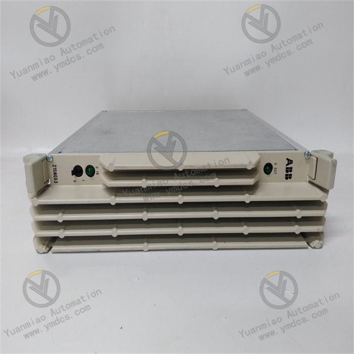
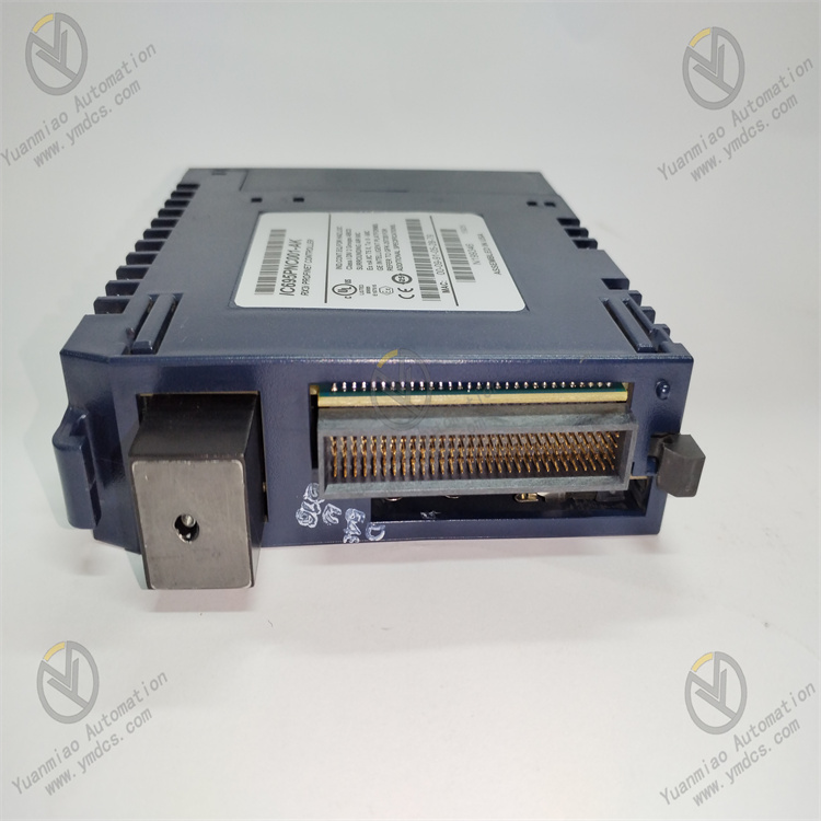
GE IC695PNC001
I. Overview
GE IC695PNC001 is a high-performance PROFINET communication module designed for the GE RX3i series programmable logic controller (PLC) system. Its core function is to realize high-speed data exchange between the RX3i PLC and PROFINET-compatible industrial devices (such as sensors, actuators, frequency converters, and human-machine interfaces). Integrating a dual-port Gigabit Ethernet controller and a dedicated PROFINET protocol processor, this module supports PROFINET IO Controller (IO-C) and IO Device (IO-D) modes, enabling seamless integration into PROFINET industrial networks. With industrial-grade anti-interference design and redundant communication capabilities, it is widely used in manufacturing automation, process control, intelligent production lines, and other industrial scenarios requiring reliable and real-time communication, serving as a key communication component for GE RX3i PLC to connect to the industrial Internet of Things (IIoT).
II. Key Features
1. High-Speed PROFINET Communication
- Supports PROFINET V2.3 protocol standard, compatible with IO Controller and IO Device operating modes to meet diverse network topology requirements (such as centralized control, distributed IO).
- Equipped with two Gigabit Ethernet ports (10/100/1000Mbps adaptive), supporting full-duplex communication with a data transmission latency as low as 1ms, ensuring real-time data interaction for industrial control.
- Supports PROFINET real-time (RT) and isochronous real-time (IRT) communication modes, adapting to high-precision synchronization control needs (such as multi-axis motion control, coordinated operation of production lines).
2. Redundant Design for High Reliability
- Supports communication link redundancy (Media Redundancy Protocol, MRP) and device redundancy, with automatic failover time ≤ 50ms, avoiding system downtime caused by single-point communication failures.
- Adopts industrial-grade components and enhanced Electromagnetic Compatibility (EMC) design, complying with IEC 61000-4 anti-interference standards (±4kV surge protection, ±8kV ESD protection), ensuring stable operation in complex electromagnetic environments.
- Operating temperature range: -20℃~+60℃; humidity: 5%-95% (non-condensing); MTBF (Mean Time Between Failures) ≥ 150,000 hours, meeting long-term continuous operation requirements in industrial sites.
3. Flexible Compatibility and Expansion
- Seamlessly compatible with GE RX3i series PLCs (such as IC695CPU310, IC695CPU330) and RX3i series I/O modules, supporting hot-swapping for easy system maintenance and capacity expansion without shutdown.
- Supports PROFINET device name configuration and IP address automatic assignment (DHCP/BOOTP), simplifying network deployment and device management.
- Compatible with third-party PROFINET-certified devices, supporting cross-brand integration to meet diverse industrial site equipment configuration needs.
4. Intelligent Diagnosis and Monitoring
- Built-in comprehensive self-diagnostic functions, real-time monitoring of network connection status, protocol communication status, module power supply, and port working status. Fault information is fed back through PLC status registers and LED indicators for quick troubleshooting.
- Supports PROFINET network status monitoring, including device online status, data transmission rate, and error packet statistics, facilitating network operation and maintenance through upper-layer software (such as GE Proficy Machine Edition).
5. Easy Configuration and Maintenance
- Configurable via GE Proficy Machine Edition (PME) software, providing a visual configuration interface for setting communication parameters, network topology, and redundancy strategies without complex programming.
- Supports online firmware upgrades and configuration parameter backup/restoration, enabling remote maintenance and reducing on-site operation costs.
III. Technical Specifications
| Category | Detailed Specifications |
|---|---|
| Product Type | GE RX3i series PROFINET communication module |
| Core Functions | PROFINET communication, data exchange between PLC and industrial devices, network redundancy |
| Protocol Support | PROFINET V2.3 (IO Controller/IO Device modes); supports RT/IRT communication; compatible with MRP redundancy protocol |
| Communication Ports | 2 x Gigabit Ethernet ports (RJ-45); communication rate: 10/100/1000Mbps (auto-negotiation) |
| Communication Performance | Transmission latency: ≤1ms (RT mode); failover time: ≤50ms (MRP redundancy); maximum number of connected IO Devices: 64 |
| Electrical Parameters | Operating Power Supply: 24VDC (±10%); Power Consumption: ≤8W (full load); Power Interface: RX3i backplane power supply |
| Compatibility | Compatible with GE RX3i series PLCs and I/O modules; supports third-party PROFINET-certified devices |
| Environmental Adaptability | Operating Temperature: -20℃~+60℃; Storage Temperature: -40℃~+85℃; Humidity: 5%-95% (non-condensing); Vibration: 10g (10-2000Hz) |
| Installation Method | RX3i series standard backplane insertion (compatible with RX3i 3-slot/5-slot/7-slot racks) |
| Physical Dimensions | Width: 36mm; Height: 100mm; Depth: 160mm (excluding connectors) |
| Weight | Approximately 0.3kg |
| Certifications | CE, UL, CSA; Complies with IEC 61158-3-10, IEC 61784-1, IEC 61000-4 standards |
| Diagnostic Functions | Self-diagnosis (module status, power supply, ports); network status monitoring; fault alarm and recording |
IV. Working Principle
The core working logic of IC695PNC001 is "Protocol Parsing → Data Transmission → Redundancy Control → Diagnostic Feedback", with the specific process as follows:
- Protocol Initialization and Configuration: After the module is powered on, it loads the PROFINET protocol stack and configuration parameters (such as IP address, device name, operating mode) set via Proficy Machine Edition software, establishing a communication connection with the RX3i PLC backplane.
- Data Exchange with PLC: The module receives control instructions (such as device control commands, data read/write requests) from the RX3i CPU through the backplane bus, and transmits collected industrial device data (such as sensor signals, actuator status) to the CPU for logical operation.
- PROFINET Network Communication: Based on the PROFINET protocol, the module exchanges data with external PROFINET devices (IO Devices) through Gigabit Ethernet ports:
- In IO Controller mode: The module sends control commands and parameter configurations to IO Devices, and collects real-time data from IO Devices;
- In IO Device mode: The module receives control commands from the upper PROFINET IO Controller and feeds back local device status data.
Redundancy Control: When configured with MRP redundancy, the two Ethernet ports establish main and standby communication links. The module real-time monitors link status; if the main link fails, it automatically switches to the standby link within ≤50ms to ensure uninterrupted data transmission.
- Diagnostic and Feedback: The module continuously monitors its own working status (power supply, ports, protocol stack) and network communication status (link connectivity, data transmission errors). If an abnormality is detected, it generates a fault code, stores it in the status register, and triggers the corresponding LED indicator alarm. The PLC or upper-layer software reads the fault information to realize troubleshooting and maintenance.
V. Operation Guide
1. Installation Steps
Installation Environment
- Install the module in the RX3i series standard rack, which should be placed in a dry, well-ventilated control cabinet, away from high-temperature heat sources (such as power modules, frequency converters) and strong electromagnetic interference sources (such as contactors, relays).
- Reserve ≥5mm heat dissipation gap around the module to ensure air circulation and avoid overheating.
Mechanical Installation
- Insert the module vertically into the RX3i rack backplane along the guide rail, ensuring the module is fully inserted and the locking clip is securely fastened to prevent poor contact caused by vibration.
- Confirm that the rack power supply is disconnected before installation to avoid damage to the module or rack.
Wiring Specifications
- Network Wiring: Use industrial shielded Cat5e/Cat6 Ethernet cables to connect the module's RJ-45 ports to the PROFINET switch or target device. The shield layer should be grounded at one end (ground resistance ≤4Ω) to enhance anti-interference performance.
- Redundancy Wiring: For MRP redundancy configuration, connect the two Ethernet ports of the module to different switches respectively to form main and standby links. Label the cables clearly (e.g., "Port 1 - Main Link", "Port 2 - Standby Link") for maintenance.
- Grounding Requirements: Ensure the control cabinet and rack are properly grounded, with a grounding resistance ≤4Ω, to prevent electrostatic discharge or electromagnetic interference from damaging the module.
2. Configuration and Debugging
Hardware Compatibility Check
- Confirm that the module is compatible with the RX3i PLC model (such as CPU model, rack model) and the PROFINET device model to be connected.
- Check that the rack power supply voltage is within the range of 24VDC±10% to meet the module's power requirements.
Software Configuration (via Proficy Machine Edition)
- Install Proficy Machine Edition software (version V9.0 or above), create a new RX3i project, and add the IC695PNC001 module to the project configuration.
- Basic Communication Configuration:
- Set the module's PROFINET device name and IP address (static IP or DHCP automatic acquisition);
- Select the operating mode (IO Controller/IO Device) and configure network parameters (such as subnet mask, gateway).
- Redundancy Configuration (If Required):
- Enable MRP redundancy function, set the redundancy role (Manager/Client) and link switching time;
- Configure the main and standby link ports and associate them with the PROFINET network.
- Device Association Configuration:
- In IO Controller mode: Add PROFINET IO Devices to the project, configure device IP addresses and signal mapping relationships (such as input/output data addresses);
- In IO Device mode: Configure the module's local input/output data mapping to the upper IO Controller.
- Download the configuration file to the RX3i PLC, and restart the PLC to make the configuration take effect.
Commissioning and Testing
- Communication Connectivity Test:
- Use the "Ping" command on the upper computer to verify the network connectivity between the module and PROFINET devices (packet loss rate ≤0.1%);
- Check the module's LED indicators: The power light (green) is always on, and the network link lights (yellow) are flashing, indicating normal communication.
- Data Transmission Test:
- Send test commands through the PLC program to read/write data from PROFINET devices, verifying the accuracy and real-time performance of data transmission (transmission latency ≤1ms);
- Simulate sensor signal input, observe whether the PLC can correctly receive and process the data, and whether the control instructions can be accurately executed by the actuators.
- Redundancy Switching Test:
- Disconnect the main communication link, check whether the module automatically switches to the standby link within ≤50ms, and confirm that data transmission is not interrupted;
- Restore the main link, verify that the module can switch back to the main link normally.
- Diagnostic Function Test:
- Simulate network disconnection, port failure and other fault scenarios, check whether the module generates corresponding fault codes and triggers LED alarms;
- Read the fault information through the PLC status register to verify the accuracy of fault diagnosis.
3. Operation and Maintenance
Status Monitoring
- Monitor the module's operating status through Proficy Machine Edition software or rack LED indicators:
- Normal Status: Power light (green) is always on, network link lights (yellow) are flashing, fault light (red) is off;
- Fault Status: Fault light (red) is on or flashing, and the specific fault type can be queried through the PLC status register (e.g., "F01 - Network Disconnection", "F02 - Protocol Error").
Regular Maintenance
- Monthly:
- Use dry compressed air to clean dust on the module surface and Ethernet port contacts to avoid poor contact caused by dust accumulation;
- Check the tightness of network cable connections and the integrity of the shield layer, and re-tighten loose terminals.
- Every 6 Months:
- Verify the module's communication performance, including transmission latency and packet loss rate, and re-calibrate the signal mapping relationship if necessary;
- Back up the module's configuration parameters and firmware to prevent data loss due to unexpected failures.
- Annually:
- Check whether the module's components (such as capacitors, connectors) are aging (e.g., capacitor bulging, connector oxidation), and replace them if necessary;
- Update the module's firmware to the latest stable version according to GE's official update prompts to optimize performance and fix known bugs.
Notes
- Do not plug or unplug the module when the rack is powered on, as this may damage the module or PLC backplane. Before maintenance, cut off the power supply and wait for 3 minutes (for discharge completion).
- When modifying configuration parameters or upgrading firmware, back up the original data first to avoid system malfunctions caused by incorrect configurations. The modified parameters take effect only after the PLC is restarted; ensure that the on-site equipment is in a safe state before restarting.
- For modules that have been idle for more than 6 months, perform a comprehensive functional test (including power supply, communication, and redundancy functions) before use to confirm no abnormalities.
4. Common Troubleshooting
| Fault Phenomenon | Possible Causes | Troubleshooting Methods |
|---|---|---|
| Module Failed to Communicate (Ping Unreachable) | IP Address Conflict, Incorrect Network Wiring, Protocol Mismatch | Check whether the module's IP address conflicts with other devices and ensure it is in the same network segment; recheck the network cable connection and replace the damaged shielded cable; confirm that the PROFINET protocol version is consistent with the connected device and reconfigure the protocol parameters. |
| Fault Light On (Network Communication Error) | Network Link Disconnection, Switch Failure, Port Damage | Check whether the network cable is broken or loose, and re-plug or replace the cable; test whether the switch port is working normally and switch to a spare port; check whether the module's Ethernet port is oxidized or damaged, and replace the module if necessary. |
| Slow Data Transmission or High Latency | Low Network Bandwidth, Electromagnetic Interference, Incorrect Protocol Configuration | Upgrade the switch to Gigabit Ethernet to increase bandwidth; replace the high-quality shielded cable and route it away from power cables (distance ≥30cm); switch to PROFINET RT/IRT mode and optimize the network topology to reduce intermediate nodes. |
| Redundancy Switching Failure | Incorrect Redundancy Configuration, Standby Link Fault, MRP Protocol Not Enabled | Recheck the redundancy configuration parameters (such as MRP role, switch time) to ensure consistency with the network requirements; verify the connectivity of the standby link and repair the faulty link; enable the MRP protocol in the software and re-download the configuration. |
| Data Transmission Error or Loss | Signal Interference, Loose Wiring, Incorrect Signal Mapping | Check the shield layer grounding of the network cable and enhance anti-interference measures; re-tighten the wiring terminals to ensure reliable connection; verify the signal mapping relationship between the module and PROFINET devices and correct the incorrect mapping address. |
| Power Light Off (No Power Supply) | Incorrect Power Wiring, Abnormal Power Supply Voltage, Power Interface Fault | Check the rack power supply wiring and ensure the voltage is within the range of 21.6VDC~26.4VDC; test the power supply module output and replace the faulty power supply; check whether the module's power interface is in good contact and reinsert the module firmly |