Description
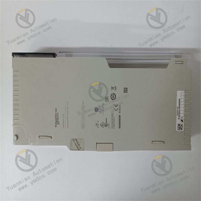
GE IC693CPU364
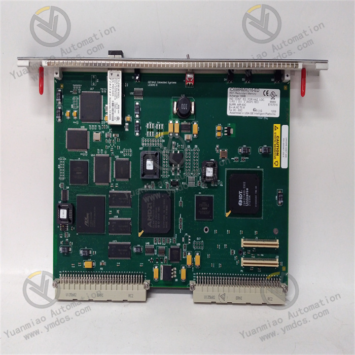
I. Overview
II. Key Features
High-Performance Computing and Multi-Task Processing
- Equipped with a 32-bit RISC industrial processor, with an operating speed of 0.1μs per boolean instruction. Supports multiple programming methods such as complex ladder logic, function blocks (FB), and structured text (ST), enabling efficient execution of large-scale control logic (supporting up to 256KB user programs).
- Supports multi-task parallel processing, allowing division into 8 priority tasks (including 1 system task + 7 user tasks) with a task switching time ≤1ms, meeting the synchronous execution requirements of timing control, interlock protection, data acquisition, and other multi-scenario applications.
Large-Capacity Storage and Flexible Expansion
- Built-in 256KB user program memory (Flash ROM, non-volatile) and 128KB data memory (RAM, with super capacitor backup, data retention ≥72 hours after power failure), supporting expansion to 512KB program memory.
- Compatible with the full range of Series 90-30 I/O modules (analog, digital, special function modules), supporting a maximum of 2048 digital I/O points or 256 analog I/O channels. Enables local rack expansion and distributed I/O expansion (via Genius Bus or Profibus-DP), adapting to control systems of different scales.
Multi-Protocol Communication and Data Interaction
- Integrates dual-port RS485 communication interfaces, supporting protocols such as Genius Bus, Modbus RTU, and DF1. Can connect to HMI, touch screens, remote I/O modules, and third-party devices; optional Ethernet communication module (e.g., IC693CMM311) supports EtherNet/IP and Modbus TCP protocols, enabling data interaction with upper-level systems (SCADA, MES).
- Supports multiple communication modes including point-to-point communication, master-slave communication, and broadcast communication. Communication rates up to 1Mbps (RS485) and 10/100Mbps (Ethernet expansion), meeting the interconnection needs of multiple devices in industrial sites.
High Reliability and Fault-Tolerant Design
- Adopts industrial-grade components and enhanced electromagnetic compatibility (EMC) design, passing IEC 61000-4 anti-interference tests (surge ±2kV, ESD ±8kV). Operating temperature range: 0℃~+60℃; humidity: 5%-95% (non-condensing); MTBF (Mean Time Between Failures) ≥150,000 hours.
- Built-in fault-tolerant functions such as program self-check, memory verification, and I/O communication diagnosis. Supports redundant configuration (dual CPU hot standby) with seamless switching in case of faults to ensure continuous system operation; super capacitor backs up data to avoid loss of critical data due to power failure.
Easy Programming and Maintenance
- Compatible with GE Fanuc Logicmaster 90-30 and Proficy Machine Edition (PME) programming software, supporting online programming, monitoring, debugging, and program upload/download. Provides a multi-language programming environment including ladder logic, function blocks, and instruction list, adapting to the operating habits of different engineers.
- Equipped with LED status indicators (power, run, fault, communication) on the top of the module, providing real-time feedback on working status; supports fault code storage (recording up to 50 fault information entries), which can be read via programming software for quick problem location.
III. Technical Specifications
| Category | Detailed Specifications |
|---|---|
| Product Type | High-performance CPU module of Series 90-30 series |
| Core Functions | Logical operation, data processing, I/O module management, communication interaction, control command execution |
| Processor Configuration | 32-bit RISC industrial processor, operating speed of 0.1μs per boolean instruction |
| Storage Configuration | Program memory: 256KB Flash ROM (expandable to 512KB); Data memory: 128KB RAM (super capacitor backup) |
| Task Processing | Supports 8 priority tasks (1 system + 7 user), task switching time ≤1ms |
| I/O Expansion Capacity | Maximum digital I/O: 2048 points; Maximum analog I/O: 256 channels; Supports local rack and distributed expansion (Genius Bus/Profibus-DP) |
| Communication Interfaces | Built-in 2 RS485 ports (supports Genius Bus, Modbus RTU, DF1); Optional Ethernet module (EtherNet/IP, Modbus TCP) |
| Communication Rates | RS485: Up to 1Mbps; Ethernet expansion: 10/100Mbps (auto-negotiation) |
| Electrical Parameters | Operating power supply: 5VDC (provided by Series 90-30 power supply module); Power consumption: ≤8W (full load) |
| Compatibility | Compatible with full range of Series 90-30 I/O modules and communication modules; Compatible with Logicmaster 90-30 and PME software |
| Environmental Adaptability | Operating temperature: 0℃~+60℃; Storage temperature: -40℃~+85℃; Humidity: 5%-95% (non-condensing); Vibration: 10g (10-2000Hz) |
| Installation Method | Series 90-30 standard rack plug-in installation (compatible with 3-slot/5-slot/7-slot racks) |
| Physical Dimensions | Width: 36mm; Height: 130mm; Depth: 180mm (excluding connectors) |
| Weight | Approximately 0.5kg |
| Diagnostic Functions | Program self-check, memory verification, I/O communication diagnosis, power fault monitoring, communication abnormality alarm |
| Status Indicators | Power light (PWR, green), Run light (RUN, yellow), Fault light (FAULT, red), Communication light (COMM, green) |
IV. Working Principle
Program Loading and Initialization: After the module is powered on, it loads user programs (ladder logic/function blocks, etc.) and system configuration parameters from the Flash ROM, completing initialization operations such as memory initialization, I/O module identification, and communication protocol startup. Initialization time ≤3 seconds.
- Data Acquisition: Through the rack bus and expansion bus, real-time read input signals (such as sensor status, analog data) from local I/O modules and distributed I/O modules, and store them in the input image area of the data memory.
Logical Operation: According to the control logic preset in the user program (such as interlock conditions, PID regulation, timing control), combined with data from the input image area and internal register data, perform arithmetic operations, logical judgments, and other processing to generate control results.
- Command Execution: Write the operation results to the output image area of the data memory, and send them to the I/O modules via the bus to drive actuators (such as solenoid valves, control valves, motor starters) to act, realizing industrial on-site control.
Communication Interaction: Through RS485 interfaces or expanded Ethernet interfaces, perform data interaction with HMI, upper-level SCADA systems, and third-party devices, uploading on-site data (such as equipment status, process parameters) and receiving remote control commands and parameter updates.
- Diagnosis and Fault Tolerance: Real-time monitor program operation status, memory integrity, I/O communication links, and power supply stability. If an abnormality is detected (such as program error, I/O disconnection, communication interruption), immediately trigger the fault light alarm, store the fault code, and execute preset fault-tolerant strategies (such as shutdown protection, standby mode switching).
V. Operation Guide
1. Installation Steps
Installation Environment
- Install in a dry and well-ventilated PLC control cabinet, away from strong electromagnetic interference sources (such as frequency converters, power modules) and high-temperature heat sources. Reserve a heat dissipation gap of ≥10mm on both sides, and ensure good ventilation in the control cabinet (install a fan if the ambient temperature exceeds 50℃).
Mechanical Installation
- Confirm that the rack power supply is disconnected. Insert the CPU module into the CPU slot of the Series 90-30 standard rack (usually the 2nd slot from the left of the rack, to the right of the power supply module), ensuring full contact between the module and the rack backplane contacts. Lock the fixing buckles on both sides for secure installation without looseness.
- When configuring multiple modules, the CPU module should be close to the power supply module, and I/O modules should be arranged in sequence with a spacing of ≥5mm between modules to avoid mutual heat dissipation interference.
Wiring Specifications
- Power Wiring: No separate wiring is required; 5VDC power is obtained from the power supply module (e.g., IC693PWR324) through the rack backplane. Confirm that the power supply module output is normal before installation.
- Communication Wiring: Connect the RS485 communication interface (terminals "+", "-", "GND") to external devices via shielded twisted-pair cables, with the shield layer grounded at one end (ground resistance ≤4Ω); when expanding Ethernet, wire through the optional Ethernet module using industrial-grade shielded Cat5e cables.
- Grounding Requirements: Reliably connect the rack's ground terminal to the control cabinet's ground bar with a ground resistance ≤4Ω to enhance anti-interference capability and system safety.
2. Configuration and Debugging
Hardware Compatibility Check
- Confirm the compatibility of the CPU module with the Series 90-30 power supply module, I/O modules, and rack model; check that the rack power supply voltage (5VDC) meets the CPU module requirements and that there are no conflicts in I/O module address settings.
Software Configuration (Proficy Machine Edition)
- Install PME software (Version V9.0 or above), create a new Series 90-30 project, add the IC693CPU364 module, configure the rack type, I/O module model and slot position, and import the system configuration file.
- Communication Parameter Configuration: Set the RS485 interface communication protocol (e.g., Modbus RTU), baud rate (optional 9600/19200/38400bps), data bits/parity bits/stop bits; when expanding Ethernet, configure the IP address, subnet mask, and gateway.
- Program Writing and Download: Write control programs using ladder logic/function blocks and other languages, connect to the CPU module via RS485 or Ethernet, download the program and configuration file to the module, and restart the CPU after download to make the configuration take effect.
Commissioning and Testing
- Communication Test: Monitor the communication status via PME software, establish a connection with HMI/upper-level computer, and verify that data upload and command reception are normal without packet loss or delay abnormalities.
- Logical Function Test: Simulate input signals (such as manually triggering sensors), observe whether the CPU correctly executes logical operations and whether the output signals meet expectations, verifying functions such as interlock protection and timing control.
- I/O Expansion Test: If distributed I/O is configured, check the communication connectivity between the remote I/O module and the CPU, and verify the reliability of distributed data acquisition and control command issuance.
- Diagnostic Test: Simulate I/O module disconnection, communication interruption, etc., check whether the fault light is triggered, whether the fault code is correctly recorded, and whether the fault-tolerant strategy is executed.
3. Operation and Maintenance
Status Monitoring
- Real-time monitor the operation status via module LED indicators and PME software:
- Normal Status: PWR is always on (green), RUN is flashing (yellow), FAULT is off, COMM is flashing (green, normal communication);
- Fault Status: FAULT is always on (red), and the fault code needs to be read via PME software (e.g., "F01 - Program Error", "F02 - I/O Communication Abnormality", "F03 - Memory Fault").
Regular Maintenance
- Monthly: Use dry compressed air to clean dust on the module surface and communication interface contacts, check whether the wiring terminals are loose, and whether the rack grounding is reliable.
- Every 6 Months: Back up user programs and configuration files (store on a computer or USB drive), verify the consistency between the program version and on-site requirements; test the super capacitor data retention function (restore power after 72 hours of power failure and check if data is lost).
- Annually: Inspect whether the internal capacitors and connectors of the module are aging (such as capacitor bulging, contact oxidation); update PME software and CPU firmware (if required) to optimize system performance.
Notes
- Do not plug/unplug the CPU module or modify wiring while powered on. Before maintenance, cut off the rack power supply and wait for 3 minutes (for discharge completion) to avoid damaging the module or losing data.
- Before modifying programs or configuration parameters, be sure to back up the original data to prevent system failures caused by incorrect configurations; when modifying programs online, ensure that on-site equipment is in a safe state.
- For modules idle for more than 6 months, conduct a comprehensive inspection (power supply, communication, program operation) before commissioning, and confirm that the super capacitor performance is normal before connecting to the system.
4. Common Troubleshooting
| Fault Phenomenon | Possible Causes | Troubleshooting Methods |
|---|---|---|
| PWR light is off (no power supply) | Power supply module fault, poor contact with rack backplane, abnormal power supply voltage | Check if the power supply module output is 5VDC; re-plug the CPU module to ensure good contact; test with a spare power supply module. |
| RUN light is off (not running) | Program error, configuration parameter conflict, memory fault | Read the fault code via PME software to troubleshoot program syntax errors; verify configuration parameters (such as I/O addresses); check if the data memory is damaged and format the memory if necessary. |
| FAULT light is always on (fault alarm) | I/O module fault, communication link interruption, program abnormality | Disconnect I/O modules one by one to troubleshoot the faulty module; check if the communication cable is loose/damaged, rewire or replace it; troubleshoot program logic errors, repair and re-download. |
| Communication failure (COMM light is off) | Mismatched communication parameters, interface damage, cable fault | Verify the communication protocol, baud rate, and other parameters between the CPU and external devices; test the communication interface conductivity with a multimeter; replace the shielded communication cable and spare interface. |
| Data loss (after power failure) | Super capacitor failure, backup function not enabled | Test the super capacitor performance and replace if failed; check if the data backup configuration in PME software is enabled to ensure critical data is stored in Flash ROM. |
| I/O module unresponsive | I/O address conflict, module not recognized, bus fault | Verify I/O module address settings to avoid conflicts; re-plug the I/O module and check if the rack bus is loose; diagnose the I/O module connection status via PME software. |