Description
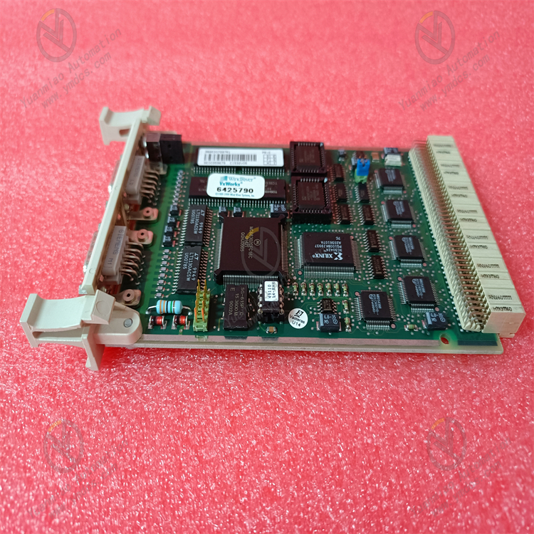
GE IC695ALG808
I. Overview
GE IC695ALG808 is an analog input/output (I/O) mixed module. Its core function is to achieve high-precision acquisition (input) of various analog signals and accurate output of control signals in industrial fields, establishing a core channel for analog signal interaction in PLC systems. Integrating 8 analog input (AI) channels and 8 analog output (AO) channels, this module supports multiple standard industrial signal types and features high resolution, strong anti-interference capabilities, and flexible configuration. It is seamlessly compatible with all CPUs of the RX3i series PLCs and Proficy Machine Edition (PME) configuration software. Widely used in chemical process control, metallurgical automation, energy monitoring, intelligent equipment, and other scenarios, it serves as a key analog processing component connecting sensors, actuators, and PLC controllers.
II. Key Features
Multi-Channel Mixed Design with Full Signal Type Coverage
- 8 Analog Input (AI) Channels: Compatible with 4-20mA current signals, 0-10V/±10V voltage signals, thermocouples (Types J/K/T/E/R/S/B), and RTDs (Pt100/Pt1000, 2/3/4-wire). Each channel can be independently configured with signal types, adapting to various sensors such as temperature, pressure, and flow sensors.
- 8 Analog Output (AO) Channels: Supports 4-20mA current output (load impedance ≤500Ω) and 0-10V/±10V voltage output (load impedance ≥1kΩ). It can directly drive actuators such as control valves, frequency converters, and servo drives, meeting closed-loop control requirements.
High-Precision Acquisition and Output with Leading Control Accuracy
- Input resolution up to 16 bits, measurement accuracy of ±0.05% FS (at 25℃) and ±0.1% FS (full temperature range). The sampling rate is configurable (10Hz-100Hz per channel), ensuring accurate capture of weak analog signals.
- Output resolution of 16 bits, output accuracy of ±0.1% FS, and output ripple ≤10mVp-p. The signal stability enables precise regulation of actuators.
Enhanced Anti-Interference and Isolation Design
- Electrical isolation between channels (isolation voltage: 250V AC) and between the module and system backplane (500V AC), effectively suppressing common-mode and differential-mode interference in industrial environments. Complies with IEC 61000-4 anti-interference standards (surge ±2kV, ESD ±8kV).
- Input channels are equipped with built-in filter circuits with software-adjustable filtering intensity. Output channels feature short-circuit protection to prevent module damage due to overload.
Flexible Configuration and System Compatibility
- Full parameter configuration via Proficy Machine Edition (PME) software without hardware jumpers. Supports channel-level customization of signal types, measurement ranges, sampling rates, and filter parameters, adapting to complex application scenarios.
- Seamlessly compatible with GE RX3i series PLCs (e.g., IC695CPU310/330/430) and supports hot-swapping (requires system redundancy configuration). Can be directly inserted into RX3i standard racks (3-slot/5-slot/7-slot/10-slot) without additional adapter modules.
Intelligent Diagnosis and Easy Maintenance
- Built-in comprehensive diagnostic functions: AI channels support sensor open-circuit detection and over-range alarms; AO channels support short-circuit detection and output abnormality diagnosis. Fault information is dual-fed back via PLC status registers and LED indicators.
- Equipped with status indicators on the top of the module (power light, run light, fault light, channel status lights), enabling intuitive fault location and supporting online status monitoring and remote troubleshooting.
III. Technical Specifications
| Category | Detailed Specifications |
|---|---|
| Product Type | RX3i Series Analog Input/Output Mixed Module (8AI+8AO) |
| Core Functions | Analog signal acquisition, analog control signal output, fault diagnosis |
| Input Channels (AI) | 8 independent channels with inter-channel isolation; Supported signal types: 4-20mA (active/passive), 0-10V/±10V, thermocouples (J/K/T/E/R/S/B), Pt100/Pt1000 (2/3/4-wire) |
| Output Channels (AO) | 8 independent channels; Supported signal types: 4-20mA (load ≤500Ω), 0-10V/±10V (load ≥1kΩ) |
| Accuracy Indicators | Input accuracy: ±0.05% FS (25℃), ±0.1% FS (-20℃~+60℃); Output accuracy: ±0.1% FS |
| Resolution | 16 bits for both input and output |
| Sampling Rate | 10Hz-100Hz per channel (software-configurable, default 50Hz) |
| Isolation Characteristics | Inter-channel isolation: 250V AC; Module-backplane isolation: 500V AC; Isolation resistance ≥100MΩ (500V DC) |
| Electrical Parameters | Operating power supply: Backplane power (5VDC/24VDC, provided by RX3i rack); Power consumption: ≤12W (full load) |
| Compatibility | Compatible with GE RX3i series PLCs and Proficy Machine Edition (V9.0 and above) software |
| Environmental Adaptability | Operating temperature: -20℃~+60℃; Storage temperature: -40℃~+85℃; Humidity: 5%-95% (non-condensing); Vibration: 10g (10-2000Hz) |
| Installation Method | RX3i standard rack plug-in installation (compatible with all RX3i rack models) |
| Physical Dimensions | Width: 36mm; Height: 100mm; Depth: 165mm (excluding connectors) |
| Weight | Approximately 0.4kg |
| Diagnostic Functions | Sensor open-circuit detection, over-range alarm, output short-circuit detection, power fault monitoring, channel self-diagnosis |
| Status Indicators | Power light (PWR, green), Run light (RUN, blue), Fault light (FAULT, red), Channel status lights (8AI+8AO, yellow) |
IV. Working Principle
The core working logic of IC695ALG808 is "Analog Signal Acquisition → Signal Conditioning → Digital Conversion → PLC Interaction → Analog Signal Output + Diagnostic Closed Loop", with the specific process as follows:
- Analog Input Processing: After analog signals from industrial sensors (e.g., pressure sensors, thermocouples) are connected to AI channels, interference is suppressed via channel isolation circuits. The signals are then processed by signal conditioning circuits (filtering, amplification, cold-junction compensation for thermocouples), converted into digital signals by a 16-bit A/D converter, and finally transmitted to the PLC CPU via the RX3i backplane bus.
PLC Data Interaction: Upon receiving digital signals, the PLC CPU executes preset control logic (e.g., PID regulation) to generate control commands, which are then sent to the module via the backplane bus.
- Analog Output Processing: After receiving digital control commands, the module converts them into analog signals using a 16-bit D/A converter. The signals are optimized for stability via output conditioning circuits (amplification, driving, short-circuit protection) and finally output to actuators (e.g., control valves) to achieve closed-loop control.
- Diagnosis and Alarm: Real-time monitoring of AI channel signal amplitude (to detect over-range/open-circuit), AO channel output status (to detect short-circuit/abnormality), module power supply, and bus communication status. In case of abnormalities, fault codes are generated and uploaded to the PLC via status registers, while corresponding LED indicators are triggered for quick troubleshooting.
V. Operation Guide
1. Installation Steps
Installation Environment
- Install in an RX3i standard PLC control cabinet, away from strong electromagnetic interference sources (e.g., frequency converters, power modules) and high-temperature heat sources. Reserve a heat dissipation gap of ≥5mm on both sides to ensure good ventilation in the cabinet and avoid high-temperature accumulation.
Mechanical Installation
- Confirm that the RX3i rack power supply is disconnected. Insert the module along the rack guide rail, ensuring full contact between the module and rack backplane contacts. Lock the fixing buckles on both sides for secure installation without looseness.
- When configuring multiple modules, maintain a spacing of ≥10mm between modules to avoid mutual heat dissipation interference. Hot-swapping operations are only allowed if the system supports redundancy configuration; forced plugging/unplugging while powered on is prohibited.
Wiring Specifications
- AI Channel Wiring: Connect 4-20mA signals to "AI+" and "AI-" terminals (passive sensors require an external 24VDC power supply); connect thermocouple signals with correct polarity to "TC+" and "TC-"; connect 3-wire RTDs to "RTD+", "RTD-", and "RTD Compensation" terminals. Ground the shielded wire at one end (ground resistance ≤4Ω).
- AO Channel Wiring: Connect 4-20mA/voltage signals to "AO+" and "AO-" terminals. Select the signal type based on the actuator and ensure the load impedance meets requirements (current output ≤500Ω, voltage output ≥1kΩ).
- Grounding Requirements: Reliably connect the module's ground terminal to the control cabinet's ground bar. Common-ground the sensor shielded wire with the module's ground terminal to reduce interference.
2. Configuration and Debugging
Hardware Compatibility Check
- Confirm compatibility between the module, RX3i CPU model (e.g., IC695CPU330), and rack model. Verify that the rack power supply voltage (5VDC/24VDC) meets the module's requirements.
Software Configuration (Proficy Machine Edition)
- Create a new RX3i project, add the IC695ALG808 module, select the corresponding rack slot position, and import the module driver library.
- AI Channel Configuration: Select signal type (e.g., 4-20mA, Type K thermocouple), sampling rate, filtering intensity, and measurement range (e.g., 0-1MPa corresponding to 4-20mA) for each channel. Enable open-circuit detection/over-range alarm functions.
- AO Channel Configuration: Select output signal type (e.g., 4-20mA) and output range, bind to PLC internal control variables, and set output protection thresholds (e.g., short-circuit protection trigger current: 22mA).
- Download the configuration file to the PLC and restart the PLC for the configuration to take effect.
Commissioning and Testing
- AI Acquisition Test: Connect a standard signal source (e.g., 4-20mA signal generator, standard resistance box). Monitor collected data via PME software; the error should be ≤±0.1% FS.
- AO Output Test: Send simulated control commands via the PLC program (e.g., output 12mA corresponding to 50% opening). Measure the output signal with a multimeter to verify accuracy and stability.
- Fault Simulation Test: Disconnect the sensor wiring of an AI channel to check if the open-circuit alarm is triggered; short-circuit an AO channel to verify the effectiveness of the short-circuit protection function.
3. Operation and Maintenance
Status Monitoring
- Real-time monitor the status via module LED indicators and PME software:
- Normal Status: PWR is always on (green), RUN is always on (blue), FAULT is off, and channel status lights are flashing (normal signal).
- Fault Status: FAULT is always on (red), and the corresponding channel status light is off. Read the fault code via the PLC status register (e.g., "F01-AI1 Over-Range", "F02-AO3 Short-Circuit").
Regular Maintenance
- Monthly: Use dry compressed air to clean dust on the module surface and wiring terminals. Check for loose wiring and reliable grounding of shielded wires.
- Every 6 Months: Calibrate AI/AO channel accuracy with a standard signal source. If the deviation exceeds ±0.2% FS, re-calibrate via PME software; back up the module configuration file.
- Annually: Inspect internal capacitors and connectors for aging, test channel isolation performance, and update the module firmware (if required).
Notes
- Do not plug/unplug the module or modify wiring while powered on. Before maintenance, cut off the rack power supply and wait for 3 minutes (for discharge completion).
- Distinguish the positive and negative poles when wiring thermocouples to avoid measurement deviations due to reverse connection; ensure RTD compensation wires match the signal wire specifications to reduce errors.
- For modules idle for more than 6 months, fully test channel functions and accuracy before commissioning to confirm no abnormalities.
4. Common Troubleshooting
| Fault Phenomenon | Possible Causes | Troubleshooting Methods |
|---|---|---|
| No data collected by AI channels | Incorrect wiring, sensor fault, unconfigured channels | Verify the matching between wiring and signal types; test with a sensor of the same model; check if AI channels are correctly configured in PME software. |
| Large deviation in collected data | Uncalibrated channels, electromagnetic interference, insufficient sensor accuracy | Re-calibrate channels with a standard signal source; replace shielded wires and ground at one end, routing away from power cables; replace with high-precision sensors. |
| No output signal from AO channels | Incorrect output type configuration, actuator fault, internal module fault | Check the output signal type setting in PME software; test the actuator's load impedance and working status; test with a module of the same model. |
| Severe fluctuation of output signal | Improper control logic parameters, electromagnetic interference, unstable load | Optimize PLC control logic (e.g., adjust PID parameters); increase output filtering intensity; check actuator load stability. |
| FAULT light is always on (channel fault) | Sensor open-circuit, output short-circuit, channel damage | Check the continuity of sensor wiring for AI channels; troubleshoot short-circuits in AO channels; disable the faulty channel via PME software and observe if the system recovers. |
| Module fails to communicate | Poor contact with the rack backplane, incorrect configuration, CPU fault | Re-plug the module to ensure good contact; verify consistency between the module slot configuration and the PME project; check the PLC CPU operating status. |