Description
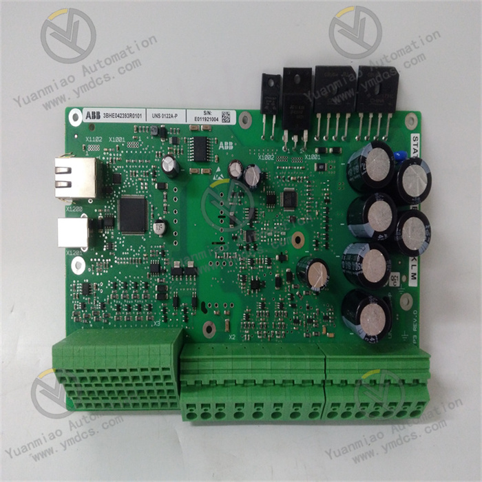
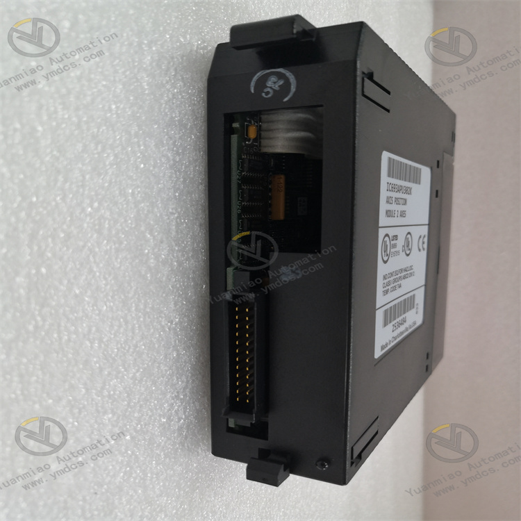
GE IC693APU302P
I. Overview
GE IC693APU302P is a power supply module belonging to the PACSystems RX3i/Series 90-30 product line. As the core power supply unit of the system, it is specifically designed for industrial automation control systems. Its primary function is to convert external AC/DC power into stable DC power required by the PLC system, providing continuous and reliable power support for all backplane-mounted devices such as CPU modules, I/O modules, and communication modules. Equipped with industrial-grade features including wide voltage input, redundant backup, and fault alarm, this module is compatible with the GE Proficy Machine Edition platform and supports hot-swap maintenance. It is widely used in industrial scenarios with strict requirements for power supply stability, such as chemical, power, manufacturing, and rail transit industries, and serves as a key component for building highly reliable distributed control systems.
II. Key Features
Wide Voltage Input & Multi-Output Adaptability
- Supports dual input modes: AC input (85-264V AC) and DC input (120-300V DC), adapting to power grid standards in different regions worldwide without the need for additional transformers, ensuring high installation flexibility.
- Provides two stable DC output channels: 5V DC (for powering backplane logic circuits and core module chips) and 24V DC (for auxiliary power supply to external sensors and actuators), meeting both internal and external system power requirements.
High Reliability & Redundancy Design
- Supports parallel redundant operation of two modules. When the main power supply module fails, the standby module switches seamlessly with a switching time <5ms, ensuring uninterrupted system power supply. The Mean Time Between Failures (MTBF) exceeds 100,000 hours.
- Built-in protection circuits against overvoltage, overcurrent, short circuit, overtemperature, and undervoltage. Automatically cuts off output and triggers an alarm when input voltage is abnormal, output is short-circuited, or module temperature exceeds the limit, preventing damage to load equipment.
Intelligent Monitoring & Fault Feedback
- Equipped with power status indicators (Power/OK, Fault) and a fault relay output for real-time feedback of power supply status. Supports uploading power supply parameters (input voltage, output current, module temperature) to the CPU via the backplane bus, enabling remote monitoring by users through upper computer software.
- Built-in self-diagnostic function that automatically detects internal module circuit faults (e.g., fan failure, capacitor aging) and provides timely early warnings via alarm signals, facilitating preventive maintenance.
Industrial-Grade Environmental Adaptability
- Features a wide temperature design, enabling stable operation in harsh environments ranging from -20℃ to 60℃. With an IP20 protection rating, it is dustproof and tamper-proof. Its electromagnetic interference (EMI) resistance complies with EN 55011/EN 55022 industrial standards, adapting to complex electromagnetic environments.
- Supports hot-swap operation, allowing module replacement without shutting down the system, reducing system maintenance downtime and improving operation and maintenance efficiency.
Strong System Compatibility
- Perfectly compatible with GE PACSystems RX3i/RX7i and Series 90-30 platforms, enabling flexible combination with digital I/O, analog modules, communication modules, etc., to build large-scale control systems.
- Adopts a standard design for the backplane interface, compatible with all modules in the series, featuring simplified wiring and easy installation without the need for additional adapter accessories.
III. Technical Specifications
| Category | Detailed Specifications |
|---|---|
| Input Specifications | AC Input: 85-264V AC (47-63Hz); DC Input: 120-300V DC |
| Output Specifications | Main Output: 5V DC / 8A (Backplane Power Supply); Auxiliary Output: 24V DC / 2A (External Device Power Supply) |
| Output Accuracy | 5V Output: ±0.5%; 24V Output: ±1.0% |
| Ripple and Noise | 5V Output: ≤50mVp-p; 24V Output: ≤100mVp-p |
| Protection Functions | Overvoltage Protection, Overcurrent Protection, Short Circuit Protection, Overtemperature Protection, Undervoltage Protection |
| Redundancy Support | Supports parallel redundancy of two modules; Redundancy switching time <5ms |
| Environmental Adaptability | Operating Temperature: -20℃~60℃; Storage Temperature: -40℃~85℃; Humidity: 5%-95% (non-condensing) |
| Physical Specifications | Dimensions: Approx. 115mm×100mm×25mm; Weight: Approx. 0.5kg; Mounting Method: DIN Rail/Screw Fixation |
| Power Consumption | Typical Power Consumption: 50W; Maximum Power Consumption: 60W |
| Response Time | Input Voltage Transient Recovery Time: <10ms; Load Transient Response Time: <5ms |
IV. Working Principle
The core working logic of the IC693APU302P is "Input Power → Rectification and Filtering → Voltage Regulation and Conversion → Stable Output + Status Monitoring," with the specific process as follows:
Power Input and Rectification
After external AC/DC power is connected to the module, it first passes through an EMI filter to suppress electromagnetic interference. AC input is converted to DC voltage via a bridge rectifier circuit, while DC input directly enters the filtering stage. Subsequently, electrolytic capacitors filter out ripples and noise from the voltage, obtaining a stable DC bus voltage.
Voltage Regulation and Conversion
The stable DC bus voltage enters the DC-DC conversion unit, which converts high-voltage DC into 5V DC and 24V DC required by the system using high-frequency switching power supply technology (PWM Pulse Width Modulation):
- The 5V output uses a precision voltage reference and feedback adjustment circuit to ensure output accuracy within ±0.5%, powering core devices such as the CPU and I/O modules on the backplane.
- The 24V output is achieved through an independent voltage regulation circuit with an accuracy of ±1.0%, providing auxiliary power for external sensors, solenoid valves, and other actuators.
Redundancy Control (In Redundant Configuration)
When the system is configured with dual-module redundancy, the built-in redundancy control circuit of the module real-time monitors its own output status and the working status of the other module. Current sharing technology ensures balanced distribution of load current between the two modules. If the main module fails (e.g., abnormal output, overtemperature), the redundancy control circuit immediately triggers a switch, and the standby module seamlessly takes over power supply to ensure uninterrupted output.
Status Monitoring and Protection
The module is equipped with built-in voltage detection, current detection, and temperature detection sensors to real-time collect parameters such as input voltage, output current, and module temperature:
- If abnormalities such as overvoltage, overcurrent, short circuit, or overtemperature are detected, the protection circuit immediately cuts off the output and triggers the fault indicator to flash and the fault relay to actuate.
- During normal operation, the Power/OK indicator is steadily lit, and the detected parameters are uploaded to the PLC CPU via the backplane bus for remote monitoring by users.
V. Operation Guide
1. Installation Steps
Installation Environment
- Select a dry, well-ventilated area inside the control cabinet, away from high-temperature heat sources (e.g., frequency converters) and strong electromagnetic interference sources.
- The module must be fixed on a metal mounting plate or DIN rail to enhance heat dissipation and anti-interference capabilities.
Physical Installation
- Adopt standard 35mm DIN rail mounting or fix to the mounting plate with screws.
- The module features a compact design (115mm×100mm×25mm); maintain a minimum distance of ≥10mm between adjacent modules to ensure unobstructed heat dissipation and avoid temperature accumulation.
Wiring Specifications
- Input Wiring: Connect AC input to L and N terminals (the PE grounding terminal must be reliably grounded), and DC input to DC+ and DC- terminals. Use AWG 14-18 gauge wires for wiring, and tighten terminal screws to avoid poor contact.
- Output Wiring: The 5V output automatically powers system modules via the backplane, requiring no additional wiring. The 24V auxiliary output is led out through the module terminal block to connect external sensors and actuators; ensure correct polarity (avoid reverse connection).
- Redundancy Wiring (In Redundant Configuration): Connect the redundancy interfaces of the two modules with a dedicated cable to ensure normal transmission of redundancy signals. Meanwhile, input power should be connected to different circuits separately to improve power supply reliability.
2. Software Configuration (Based on GE Proficy Machine Edition)
Module Recognition
- After installing the module on the backplane, open the Proficy Machine Edition software, create or open a project. The system will automatically recognize the IC693APU302P module in the hardware configuration interface (if not automatically recognized, manually add the "IC693APU302P" model).
Redundancy Configuration (If Required)
- Enable the "Redundant Power Supply" function in the hardware configuration interface, select the dual-module redundancy mode, and the software will automatically configure redundancy parameters without manual adjustment.
Monitoring Parameter Settings
- Enable the power monitoring function in the software, set alarm thresholds (e.g., trigger an alarm when the 5V output is below 4.75V or above 5.25V), and configure the PLC address of the fault feedback signal to facilitate the upper computer reading the alarm status.
Download and Activation
- After configuration, download the project to the PLC CPU. The module automatically loads the configuration parameters and starts working. The software real-time displays the module's operating status (input voltage, output current, redundant operation status, etc.).
3. Operation and Maintenance
Status Monitoring
- Judge the working status through the module panel indicators:
- Power/OK indicator steady on: Module operating normally.
- Fault indicator flashing: Module faulty (e.g., overtemperature, overcurrent, abnormal input).
- Redundancy status indicator (in redundant configuration): Steady on indicates redundancy readiness; flashing indicates single-module operation.
- Meanwhile, detailed operating parameters can be viewed through the upper computer software for real-time monitoring of power supply status.
Hot-Swap Operation
- When replacing the module, there is no need to shut down the system. Simply pull out the faulty module and insert a new one. The system will automatically recognize it and restore power supply (no power interruption in redundant configuration; ensure the load can be powered off for a short time in non-redundant configuration).
Regular Maintenance
- Inspect wiring terminals for looseness and cables for aging every 3 months; clean dust on the module surface to ensure unobstructed heat dissipation.
- Test the output accuracy every 1 year. If the deviation exceeds the standard value, fine-tune it using the built-in calibration potentiometer of the module (professional tools required).
- In redundant configuration, regularly switch the operating status of the main and standby modules to verify the effectiveness of the redundancy function.
4. Common Troubleshooting
| Fault Phenomenon | Possible Causes | Troubleshooting Methods |
|---|---|---|
| No Output Signal | External power not connected / Wiring error | Check if the input voltage is normal, and if the terminal wiring is secure and polarity is correct |
| Power/OK Indicator Not Lit | Module fault / Abnormal input voltage | Measure if the input voltage is within the rated range; test with a replacement module |
| Fault Indicator Flashing | Output short circuit / Overtemperature / Overcurrent | Check if the 24V output terminal is short-circuited; clean the module's heat dissipation channel; inspect if the load is overloaded |
| Redundancy Switching Failure | Redundancy cable not properly connected / Mismatched modules | Check the redundancy cable connection; confirm both modules are of the IC693APU302P model |
| Large Output Accuracy Deviation | Module aging / Calibration drift | Measure the output voltage with a multimeter; fine-tune via the calibration potentiometer or replace the module |