Description
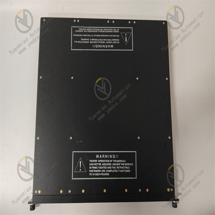
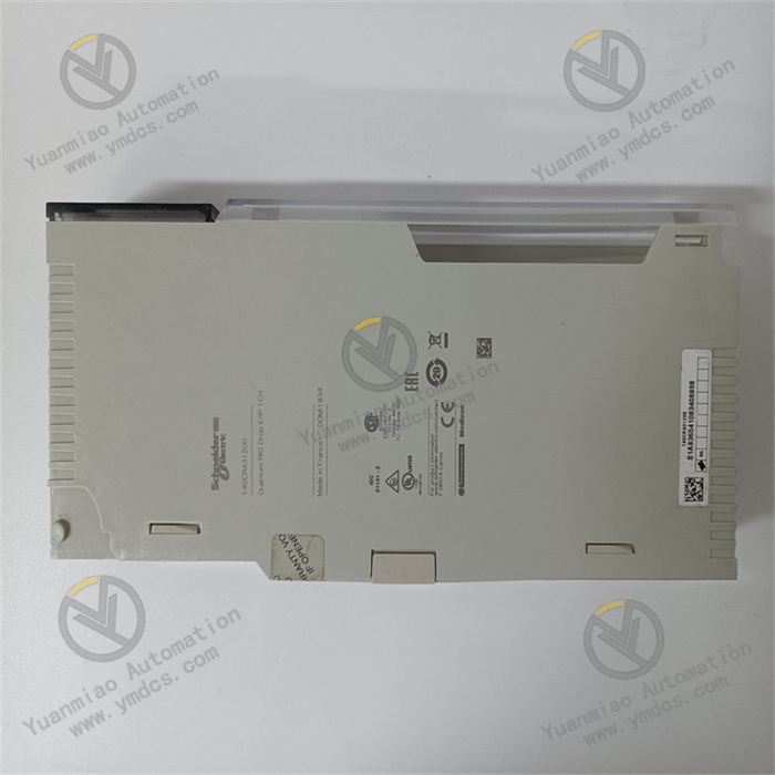
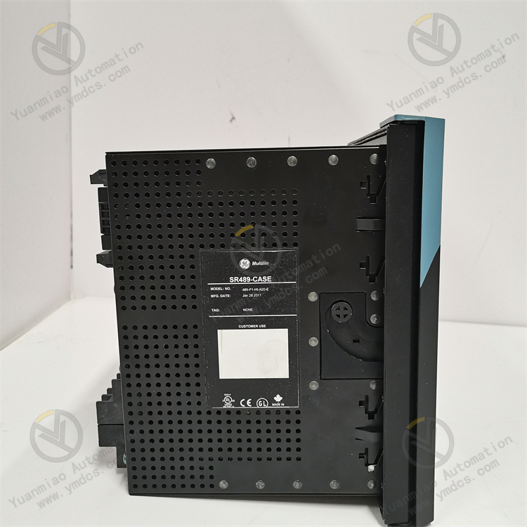
GE SR489-P1-HI-A20-E-H
The GE SR489-P1-HI-A20-E-H is a digital input module. As a core signal acquisition component in industrial automation scenarios, it is widely used in manufacturing production line status monitoring, warehouse logistics sensor signal collection, building intelligent detection, food processing equipment working condition feedback, and small-to-medium mechanical automation signal capture scenarios. This is attributed to its 20-channel high-sensitivity input, wide voltage adaptability, and strong anti-interference design. It undertakes the task of collecting digital signals from devices such as limit switches, photoelectric sensors, proximity switches, and pressure switches.
Its core advantages lie in the adoption of high-precision signal detection circuits and standardized modular design. While realizing 20-channel independent and reliable signal acquisition, it can seamlessly adapt to GE's mainstream PLC controllers, constructing a complete control link of "signal acquisition - logical operation - equipment control". It provides a cost-effective signal acquisition solution for mid-to-low-end industrial control scenarios and is a mature general-purpose digital input module applied in the industrial automation field.
- Equipped with 20 independent digital input channels, each supporting a single-ended input mode and compatible with dual voltage levels of DC 24V/120V. The voltage type can be quickly switched via the DIP switch on the side of the module.
- The input signal type supports normally open/normally closed contact signals and NPN/PNP sensor signals, adapting to different types of detection equipment.
- The input response time is configurable: ≤1ms in fast mode and ≤5ms in standard mode, meeting the needs of scenarios with different real-time requirements.
- Each channel is equipped with an independent LED status indicator. A green light on the front of the module indicates a valid input signal, while an off light indicates no input, providing intuitive and clear status feedback.
- Rated input voltage: DC 24V (allowable fluctuation range ±15%, i.e., 20.4V-27.6V) and DC 120V (allowable fluctuation range ±10%, i.e., 108V-132V).
- Rated input current per channel: ≤10mA at DC 24V and ≤5mA at DC 120V. The total full-load current of the module is ≤200mA.
- The electrical isolation between channels is ≥2500V AC/min, and the isolation between the input circuit and the backplane bus is ≥2500V AC/min, effectively blocking signal crosstalk between channels and external interference intrusion.
- It has enhanced surge suppression capability and can withstand ±2kV (1.2/50μs) surge impact.
- The electromagnetic compatibility performance complies with the IEC 61000-4 series standards, with radiated interference resistance ≥100V/m, conducted interference resistance ≥2kV (1.2/50μs), and electrostatic resistance ±8kV (contact)/±15kV (air).
- Adopts a standard PLC modular design, accurately adapting to the standard racks of GE 90-30/90-70 series PLCs (such as IC693CHS391, IC697CHS750). The module dimensions (width × height × depth) are 44.5mm × 127mm × 190.5mm, strictly following the IEC 61131-2 installation specifications.
- The shell is made of high-strength flame-retardant ABS engineering plastic, with a flame-retardant grade of UL 94 V-0, effectively improving the safety of equipment operation.
- The protection level is IP20 (module body) and IP40 (terminal block area).
- The wiring method uses front-pluggable spring terminals, supporting AWG 22-14 wires. Wiring and disassembly can be completed without tools, greatly improving installation and maintenance efficiency.
- The operating temperature range is -10℃~60℃, and the storage temperature range is -40℃~85℃, adapting to environments such as conventional industrial workshops and control rooms.
- The relative humidity is 5%~95% (no condensation), which can cope with high-humidity scenarios such as high-humidity warehouses and food processing workshops.
- The vibration resistance performance complies with the IEC 60068-2-6 standard (10~500Hz, acceleration 2g), and the impact resistance performance complies with the IEC 60068-2-27 standard (10g, 11ms half-sine wave), which can withstand conventional vibration and instantaneous impact during equipment operation.
- The heat dissipation method is natural convection heat dissipation, which can meet the full-load operation requirements without additional heat dissipation fans.
- Compatible with GE 90-30 series CPUs (such as IC693CPU313/314/315) and 90-70 series CPUs (such as IC697CPU771/772). Data communication is realized through the system backplane bus, and the communication rate is synchronized with the CPU bus rate (up to 1Mbps).
- The Mean Time Between Failures (MTBF) is ≥250,000 hours, supporting the online hot-swapping function (needing to be matched with a GE dedicated rack). Module replacement can be completed without stopping the PLC, effectively reducing production downtime losses.
- It supports collaborative work with GE series digital output modules (such as SR489-P5-LO-A20-E) to build a complete "input - operation - output" control closed loop.
- Adopts a compact circuit layout design, integrating 20 independent digital input channels within the standard PLC module width (44.5mm).
- Compared with traditional 16-channel input modules, it can increase the input point density by 25% in the same rack space, significantly reducing the space occupied by the PLC rack in the control cabinet. It is especially suitable for signal acquisition scenarios with dense points such as production lines and assembly lines.
- Each channel has an independent wiring interface and clear number marking, facilitating on-site wiring construction and later fault troubleshooting. A single-channel fault will not affect the normal operation of other channels, ensuring the overall reliability of the system.
- Supports dual-voltage level input of DC 24V/120V. The voltage type can be quickly switched via the DIP switch on the side of the module, and it can adapt to detection equipment with different power supply specifications without replacing the module. For example, DC 24V photoelectric sensors and DC 120V limit switches can be connected simultaneously.
- It supports the input of normally open/normally closed contact signals and NPN/PNP sensor signals. The effective signal logic can be flexibly configured through PLC programming software without adjusting hardware wiring, greatly improving the versatility and adaptation range of the module.
- Each channel adopts a high-precision signal detection circuit, matched with a low-noise operational amplifier, which can accurately capture weak input signals and ensure stable identification when the signal voltage is above 80% of the rated value.
- It supports switching between two response modes: fast (≤1ms) and standard (≤5ms). The configuration can be made according to scenario requirements through programming software. The fast mode is suitable for scenarios with high real-time requirements such as high-speed production lines, while the standard mode can filter interference signals by extending the response time to improve acquisition stability.
- It has a built-in signal filtering circuit, which can effectively filter out high-frequency interference pulses and ensure the authenticity of the collected signals.
- Adopts a triple anti-interference design of "photoelectric isolation + signal filtering + metal shielding". Each input channel is equipped with an independent photoelectric isolation unit, with an isolation voltage of 2500V AC/min, which can effectively block strong electromagnetic interference generated by equipment such as frequency converters and high-power motors in industrial sites.
- The module shell is treated with a conductive coating, and combined with good grounding (grounding resistance ≤4Ω), it can further enhance the ability to resist radiated interference.
- It has surge suppression and overvoltage protection functions. The input circuit has a built-in varistor, which can absorb instantaneous overvoltage shocks and protect the internal circuit of the module from damage.
- Each channel on the front of the module is equipped with an independent LED status indicator. Maintenance personnel can intuitively judge whether there is a valid input signal in the channel through the indicator light, and quickly locate the fault channel without using testing tools such as multimeters, greatly improving fault troubleshooting efficiency.
- The front-pluggable spring terminal design allows wiring disassembly and module replacement without tools. Combined with the online hot-swapping function (needing rack support), maintenance operations can be completed without stopping the system, reducing production downtime losses.
- The modular structure design makes module maintenance more convenient, reducing later maintenance costs.
- The digital signals (on/off) from on-site detection equipment (such as photoelectric sensors and limit switches) are connected to the corresponding input channels of the module through front-pluggable spring terminals.
- The module provides a matching detection voltage for the input circuit according to the voltage level (DC 24V/120V) configured by the DIP switch, ensuring the adaptability of signal acquisition.
- Each channel is designed independently, and the access of a single-channel signal will not affect the signal acquisition of other channels.
- The accessed on-site signal first enters the photoelectric isolation unit, and electrical isolation is realized through the photoelectric conversion of the light-emitting diode and the phototransistor, completely isolating the on-site side signal from the module's internal circuit and the PLC backplane bus. This prevents on-site interference from invading the PLC controller through the signal line, ensuring the stable operation of the control system.
- The isolated optical signal is converted into a weak electrical signal, which is amplified into a standard logic level signal (0V/5V) by a high-precision operational amplifier, providing a stable signal source for the subsequent verification link.
- The amplified logic level signal enters the RC filter network to filter out high-frequency interference pulses (such as spike signals generated by electromagnetic radiation) in industrial sites.
- Then, signal delay verification is performed according to the response mode (fast/standard) configured by the programming software. In fast mode, the signal is transmitted directly; in standard mode, the instantaneous jitter signal (such as false signals generated by the bounce of mechanical switch contacts) is eliminated through 5ms delay judgment, ensuring the authenticity of the collected signal.
- The valid signal that passes the verification is transmitted to the internal data processing unit of the module.
- The data processing unit integrates the valid signals of the 20 channels into standardized data and transmits it to the PLC controller through the back bus interface. The communication rate is synchronized with the CPU bus rate (up to 1Mbps), ensuring the real-time performance of signal transmission.
- While the signal is being transmitted, the LED indicator of the corresponding channel is driven to light up, intuitively feeding back the input status of the channel and providing a visual reference for on-site maintenance personnel.
- The module has a built-in fault self-detection circuit. When faults such as input overvoltage and channel short circuit are detected, a fault signal is uploaded to the PLC controller through the bus to trigger a system alarm.
- Fault of on-site detection equipment (such as sensor damage, switch contact failure).
- Abnormal power supply of the equipment.
- Loose wiring or broken wires.
- Incorrect voltage level configuration of the module.
- Fault of the channel photoelectric isolation circuit.
- Check the power supply voltage of the on-site equipment (for example, ensure the normal power supply of DC 24V sensors), manually trigger the equipment (such as pressing the limit switch), and use a multimeter to detect the signal at the output end of the equipment to confirm whether the equipment outputs normally.
- Check the module's terminal blocks, re-plug and fasten the wires, use a multimeter to detect the continuity of the wires, and replace the broken wires.
- Verify the voltage configuration of the module's DIP switch to ensure it is consistent with the power supply voltage of the on-site equipment (for example, a DC 24V equipment corresponds to the module configured to the 24V gear).
- Connect the normally working equipment to the fault channel. If there is still no signal, it is a module channel fault, and the fault channel needs to be isolated or the module replaced.
- Check the grounding condition of the common terminal of the on-site equipment and the module to ensure good grounding (grounding resistance ≤4Ω).
- Severe electromagnetic interference in the industrial site.
- Improper configuration of the module's response mode.
- Unshielded input signal cable.
- Poor contact caused by oxidation of terminal blocks.
- Poor grounding of the module.
- Switch the module's response mode from fast mode to standard mode through programming software, extend the response time to 5ms, and filter out instantaneous interference signals.
- Replace the input signal cable with a twisted-pair shielded cable, ground one end of the shield (connect to the module's grounding terminal), and keep a distance of ≥30cm from the power cable to avoid parallel wiring.
- Polish the oxide layer on the terminal blocks with fine sandpaper, and re-fasten the wires to ensure reliable contact.
- Check the connection between the module's grounding terminal and the control cabinet's grounding bar to ensure the grounding resistance ≤4Ω and enhance the anti-interference ability.
- If the module is close to strong interference sources such as frequency converters and high-power motors, an electromagnetic shield can be installed for further protection.
- Burned-out LED indicator.
- Fault of the module's status detection circuit.
- Insufficient on-site signal voltage.
- PLC programming logic error.
- Monitor the input status of the corresponding channel through PLC programming software. If the software shows a signal but the indicator is not on, it is determined that the LED light is burned out, which does not affect the module's function. Contact after-sales service if replacement is needed.
- If the software shows no signal but the indicator is always on, check whether the on-site signal voltage reaches more than 80% of the rated value (for example, the output of a DC 24V equipment is ≥19.2V). If the voltage is insufficient, repair the equipment's power supply.
- If the status of the software and the indicator is inconsistent and this problem occurs in multiple channels, it is a fault of the module's status detection circuit, and the module needs to be returned to the factory for repair.
- Check whether the channel address configuration in the PLC control program is correct, and re-download the program to eliminate logic errors causing signal abnormalities.
- The module is not properly installed on the rack.
- Damaged backplane bus interface.
- PLC controller fault.
- Incorrect module address setting (for some models).
- Abnormal power supply of the module.
- Power off and re-install the module on the rack, ensure it is fully inserted and locked, and check that the rack bus pins are not bent or damaged.
- Replace the same-type spare module into the same slot. If the spare module communicates normally, the original module's bus interface is damaged, and the original module needs to be returned to the factory for repair.
- Restart the PLC controller, check the operation status of the controller's bus module. If all modules cannot communicate, the controller is faulty.
- For models requiring address setting, verify that the module's address DIP switch is consistent with the system configuration.
- Measure the module's power supply voltage (DC 5V or DC 24V, depending on the rack type), ensure the voltage is stable within the range of ±10% of the rated value. If the voltage is abnormal, repair the power supply circuit.
![]()