Description
GE 469-P1-HI-A20-T
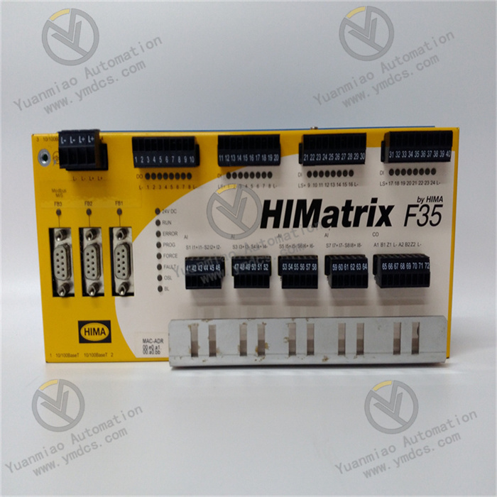
The GE 469-P1-HI-A20-T is a digital input module belonging to the GE 90-30/90-70 PLC control system architecture. As a core signal acquisition unit in industrial automation systems, it is widely used in scenarios such as manufacturing production line status monitoring, power equipment condition acquisition, chemical plant safety signal detection, building intelligent sensing data collection, and machine tool equipment signal feedback. This is attributed to its 20-channel high-density input, wide voltage compatibility, and enhanced anti-interference design. It undertakes the task of collecting and transmitting digital signals from devices such as limit switches, photoelectric sensors, proximity switches, and pressure switches.
Its core advantages lie in the adoption of photoelectric isolation technology and compact modular design. While enabling independent acquisition of 20-channel signals, it can resist strong electromagnetic interference in industrial sites. It can seamlessly interface with GE 90-30/90-70 series PLC controllers and third-party compatible systems, constructing an automated control link of "signal acquisition - logical operation - control output". It provides accurate and efficient signal acquisition support for various industrial control scenarios and is a classic digital input module widely used in the field of industrial automation.
1. Technical Parameters
1.1 Core Input Parameters
- It is equipped with 20 independent digital input channels, each supporting a single-ended input mode and compatible with dual voltage levels of DC 24V/120V. The voltage type can be switched via the module's DIP switch.
- The input signal type supports normally open/normally closed contact signals and NPN/PNP sensor signals, adapting to different types of detection equipment.
- The input response time is selectable: ≤1ms (fast response mode) and 5ms (standard mode), meeting the needs of scenarios with different real-time requirements.
- Each channel supports independent status indication, and the on-off status of the signal is displayed in real-time through the LED light on the front of the module (green light indicates input, and off indicates no input).
1.2 Electrical Performance Parameters
- The rated operating voltage is DC 24V±15% or DC 120V±10% (dual voltage optional). The rated current per input channel is ≤10mA (for DC 24V) and ≤5mA (for DC 120V), and the total full-load current of the module is ≤200mA.
- The isolation between channels is ≥2500V AC/1min, and the isolation between the input and the backplane bus is ≥2500V AC/1min, effectively avoiding signal crosstalk between channels and external interference from invading the PLC controller.
- It has a surge suppression function, capable of withstanding ±2kV (1.2/50μs) surge impacts. Its electromagnetic compatibility performance complies with IEC 61000-4 series standards, with radiated interference resistance ≥100V/m and conducted interference resistance ≥2kV.
1.3 Structural and Installation Parameters
- It adopts a standard PLC modular design, adapting to the standard racks of GE 90-30/90-70 series PLCs. The module dimensions (width × height × depth) are 44.5mm × 127mm × 190.5mm, complying with the IEC 61131-2 standard installation specifications.
- The shell is made of high-strength flame-retardant ABS engineering plastic, with a flame-retardant grade of UL 94 V-0. The protection level is IP20 (module body) and IP40 (terminal block area).
- The wiring method uses front-pluggable spring terminals, supporting AWG 22-14 specification wires. Wiring and disassembly can be completed without tools, improving installation and maintenance efficiency.
1.4 Environmental Adaptability Parameters
- The operating temperature range is -20℃~65℃, and the storage temperature range is -40℃~85℃.
- The relative humidity is 5%~95% (no condensation), enabling adaptation to extreme humidity and temperature environments such as high-humidity workshops, low-temperature warehouses, and high-temperature metallurgical workshops.
- Its vibration resistance performance complies with the IEC 60068-2-6 standard (10~500Hz, acceleration 5g), and its impact resistance performance complies with the IEC 60068-2-27 standard (15g, 11ms half-sine wave), which can withstand regular vibration and instantaneous impact during equipment operation.
- The heat dissipation method is natural convection heat dissipation, which can meet the full-load operation requirements without additional fans.
1.5 Compatibility and Reliability Parameters
- It is compatible with GE 90-30 series CPUs (such as IC693CPU313/314/315) and 90-70 series CPUs (such as IC697CPU771/772/773). Data communication is realized through the system backplane bus, and the communication rate is synchronized with the CPU bus rate (up to 1Mbps).
- The Mean Time Between Failures (MTBF) is ≥300,000 hours, and it supports the online hot-swap function (needing to be matched with a GE dedicated rack). The module can be replaced without stopping the PLC, reducing downtime losses.
2. Functional Features
2.1 20-Channel High-Density Design for Optimized Space Utilization
- It adopts a compact circuit layout and integrated component design, integrating 20 independent digital input channels within the size of a standard PLC module (44.5mm wide).
- Compared with traditional 16-channel input modules, it can increase the input point density by 25% in the same rack space, greatly reducing the space occupied by the PLC rack in the control cabinet. It is especially suitable for signal acquisition scenarios with dense points such as production lines and assembly lines.
- Each channel has an independent wiring interface and clear number marking, facilitating wiring and fault troubleshooting. A single-channel fault does not affect the normal operation of other channels.
2.2 Dual Voltage Compatibility Design for Adapting to Diverse Scenarios
- The input voltage level can be quickly switched between DC 24V and 120V via the DIP switch on the side of the module. There is no need to replace the module to adapt to detection equipment in different power supply scenarios.
- The DC 24V mode is suitable for industrial sensors (such as photoelectric switches and proximity switches).
- The DC 120V mode is suitable for devices such as limit switches and pressure switches under high-voltage working conditions.
- It supports the input of normally open/normally closed contact signals. The effective logic of the signal can be configured through PLC programming software without adjusting hardware wiring, adapting to different control logic requirements.
2.3 Enhanced Photoelectric Isolation for Improved Anti-Interference Capability
- Each input channel adopts an independent photoelectric isolation circuit, with an isolation voltage of 2500V AC/1min. It can effectively block strong electromagnetic interference in industrial sites (such as interference generated by frequency converters and high-power motors) from invading the PLC controller through input signals, ensuring the accuracy of signal acquisition in complex interference environments.
- The input circuit has a built-in RC filter network and surge suppression diode, which can filter high-frequency interference signals and suppress instantaneous voltage impacts, further improving signal stability and reducing the probability of false acquisition.
2.4 Adjustable Fast/Slow Response for Adapting to Different Real-Time Requirements
- It supports switching between two response modes: 1ms fast response and 5ms standard response, which can be configured through programming software.
- The fast response mode is suitable for scenarios with high real-time signal requirements such as high-speed production lines and machine tools, ensuring timely acquisition of status signals of high-speed moving components.
- The standard response mode is suitable for ordinary working condition monitoring scenarios. It can further filter interference signals by extending the response time, improving acquisition stability.
- The response time parameter supports independent configuration of a single channel, meeting the differentiated needs of different channels of the same module.
2.5 Convenient Maintenance and High Reliability for Reducing Operating Costs
- Each channel on the front of the module is equipped with an independent LED status indicator. A green light indicates that the channel has an effective input signal, and off indicates no input. This allows intuitive judgment of the channel's working status without the need for a multimeter, greatly improving fault troubleshooting efficiency.
- The front-pluggable spring terminal design allows wiring and module disassembly without tools. Combined with the online hot-swap function (needing rack support), the module can be replaced without stopping the PLC, reducing production line downtime losses.
- It uses military-grade high-reliability components with no mechanical wear on the contacts. The service life is synchronized with the module's MTBF, reaching more than 300,000 hours.
3. Working Principle
3.1 Signal Acquisition Link
- The digital signals (on/off) from on-site detection equipment (such as photoelectric sensors and limit switches) are connected to the corresponding channels through front-pluggable terminals.
- The module provides a matching detection voltage for the input circuit according to the voltage level (DC 24V/120V) configured by the DIP switch.
- When the contact of the detection equipment is closed or the sensor outputs an effective signal, a current loop is formed in the corresponding channel, initiating the signal conversion process.
- Each channel is designed independently, and the acquisition of signals from a single channel does not affect other channels.
3.2 Isolation and Conversion Link
- The input signal first enters the photoelectric isolation unit, and electrical isolation is achieved through the photoelectric conversion of light-emitting diodes and phototransistors. This completely isolates the on-site side signal from the module's internal circuit and the PLC backplane bus, preventing on-site interference from invading the control system through signal lines.
- The isolated optical signal is converted into a weak electrical signal, which is amplified into a standard logic level signal (0V/5V) by the signal amplification circuit to ensure stable recognition by subsequent processing units.
3.3 Filtering and Response Link
- The amplified logic level signal enters the RC filter network to filter high-frequency interference pulses (such as spike signals generated by electromagnetic radiation).
- Then, according to the response mode (1ms/5ms) configured by programming, signal delay judgment is performed to eliminate instantaneous jitter signals (such as false signals generated by the bouncing of mechanical switch contacts), ensuring the authenticity of the collected signals.
- The processed effective signal is transmitted to the internal data processing unit of the module to form standardized digital data.
3.4 Transmission and Indication Link
- The data processing unit transmits the digital data of 20 channels to the PLC controller through the bus interface on the back of the module. The transmission rate is synchronized with the PLC bus rate (up to 1Mbps), ensuring real-time data upload.
- At the same time, the status signal of each channel drives the corresponding LED indicator. The LED light is on when there is an effective input, and off when there is no input, providing intuitive status feedback for on-site operation and maintenance personnel.
- The module has a built-in fault self-test circuit. When faults such as channel short circuit and power supply abnormality are detected, fault codes are uploaded to the controller through the bus to trigger an alarm.
4. Common Faults and Solutions
4.1 Fault 1: No Signal Acquisition from a Certain Channel, LED Light Not On
Possible Causes
- Malfunction of on-site detection equipment (such as damaged sensors, failed switch contacts).
- Loose or broken wiring.
- Mismatch between the module's voltage level configuration and the equipment.
- Fault of the channel's photoelectric isolation circuit.
- Abnormal power supply of on-site equipment.
Solutions
- Check the power supply voltage of the on-site equipment (for example, ensure normal power supply for DC 24V sensors). Manually trigger the equipment (such as pressing the limit switch) and use a multimeter to detect the signal at the equipment's output terminal to confirm whether the equipment outputs normally.
- Check the module's terminal blocks, reinsert and fasten the wires to ensure good contact. Use a multimeter to detect the continuity of the wires and replace damaged wires.
- Verify the voltage configuration of the module's DIP switch to ensure it is consistent with the power supply voltage of the on-site equipment (for example, set the module's DIP switch to the 24V position for DC 24V equipment).
- Connect normally working equipment to the faulty channel. If there is still no signal, it indicates a fault in the module's channel, and the faulty channel needs to be isolated or the module replaced.
- Check the grounding of the common terminal between the on-site equipment and the module to ensure good grounding (grounding resistance ≤4Ω).
4.2 Fault 2: False Acquisition of Channels, LED Light Blinking Frequently or Turning On Falsely
Possible Causes
- Severe electromagnetic interference in the industrial site.
- Improper configuration of the module's response mode.
- Unshielded wires used for input signal cables.
- Poor contact due to oxidized terminal blocks.
- Poor grounding of the module.
Solutions
- Switch the module's response mode from 1ms fast mode to 5ms standard mode, and adjust the response time parameter through programming software to filter instantaneous interference signals.
- Replace the input signal cable with a twisted-pair shielded cable. Ground one end of the shield (connect to the module's grounding terminal) and keep a distance of ≥30cm from the power cable to avoid parallel wiring.
- Polish the oxide layer on the terminal blocks with fine sandpaper, and re-fasten the wires to ensure reliable contact.
- Check the connection between the module's grounding terminal and the control cabinet's grounding bar to ensure the grounding resistance ≤4Ω, enhancing the interference shielding effect.
- If the module is near frequency converters or high-power motors, install an electromagnetic shield to further resist radiated interference.
4.3 Fault 3: Module Cannot Communicate with the PLC Controller, No Data Upload from All Channels
Possible Causes
- The module is not properly installed on the rack.
- Damage to the backplane bus interface.
- Malfunction of the PLC controller.
- Incorrect DIP switch setting for the module address (for some models).
- Fault of the module's power supply.
Solutions
- Power off, reinsert the module into the rack to ensure the module is fully inserted and locked. Check that the rack's bus pins are not bent or damaged.
- Replace the same-type spare module into the same slot. If the spare module communicates normally, the bus interface of the original module is damaged, and the original module needs to be returned to the factory for repair.
- Restart the PLC controller and check the operation status of the controller's bus module. If all modules cannot communicate, the controller is faulty.
- For models with address DIP switches, verify that the DIP switch value is consistent with the module address configured in the system.
- Use a multimeter to measure the module's power supply voltage (DC 5V or DC 24V, depending on the rack type) to ensure the voltage is stable within the range of ±10% of the rated value. If the voltage is abnormal, troubleshoot the power supply circuit.
4.4 Fault 4: LED Light Not On but the Channel Has Signal Input
Possible Causes
- The LED indicator is burned out.
- Fault of the internal indication circuit of the module.
- Insufficient channel signal strength.
Solutions
- Monitor the input status of the corresponding channel through PLC programming software. If the software shows a signal, the LED indicator is burned out, which does not affect the channel's function. Contact after-sales service if the indicator needs to be replaced.
- If the software shows a signal but the indicator is not on, and this problem occurs in multiple channels, the internal indication circuit of the module is faulty, and the module needs to be returned to the factory for repair.
- Measure the output signal voltage of the on-site equipment to ensure the voltage reaches more than 80% of the module's rated input voltage (for example, the output of DC 24V equipment is ≥19.2V). If the voltage is insufficient, troubleshoot the equipment's power supply or replace the equipment.