Description
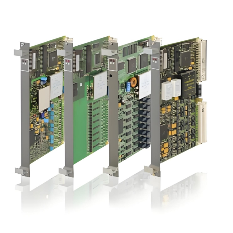
GE DS200DDTBG1A
The GE DS200DDTBG1A is an industrial-grade digital input/output (I/O) module, serving as a core I/O component of the Mark VIe series Distributed Control System (DCS). It is positioned as the "Digital Signal Acquisition and Control Execution Terminal for Large-Scale Industrial Equipment". Its core function is to achieve high-precision acquisition of digital signals and high-reliability command output in industrial sites. On one hand, it accurately collects digital status signals (such as equipment start-stop status, fault signals, and position signals) from on-site sensors, travel switches, limit switches, and other devices, and uploads them to the controller module. On the other hand, it receives control commands issued by the controller to drive the actions of executive mechanisms such as contactors, solenoid valves, and indicator lights, building a digital signal interaction bridge between on-site equipment and the core unit of the control system. With its high-density I/O channel design, dual redundancy architecture, and strong anti-interference performance, this module meets the digital monitoring needs of large rotating machinery (such as gas turbines and steam turbines) and complex process flows in fields like electric power, petrochemicals, and metallurgy. It is a key execution unit of the GE Mark VIe control system for realizing equipment status monitoring and logical interlock control.
Its application scenarios are highly aligned with the digital monitoring and control needs of large-scale industrial systems:
- In the electric power generation field, as the digital I/O terminal of gas turbine generator units, it collects 32 channels of digital input signals (including the status of solenoid valves in the fuel system, start-stop signals of lubricating oil pumps, and position signals of generator circuit breakers) and outputs 16 channels of control commands to drive the actions of devices such as ignition devices, cooling fans, and alarm indicator lights. When the controller detects the "low lubricating oil pressure" input signal, it immediately issues a command through the module to cut off fuel supply and trigger a shutdown alarm.
- In the petrochemical field, it is adapted to the safety interlock system of large-scale catalytic cracking units. It collects input signals such as reactor temperature over-limit switch signals, feed pump fault signals, and valve limit signals, and outputs commands to control the actions of emergency shut-off valves and pressure relief valves, realizing rapid linkage with the Emergency Shutdown System (ESD) with a response time of ≤1ms.
- In the metallurgical field, it is used for monitoring furnace body equipment in the blast furnace ironmaking system. It collects signals such as furnace door switch status, distributor position signals, and cooling wall temperature switch signals, and outputs commands to control the actions of furnace door lifting mechanisms and distributor driving devices, ensuring the stable operation of the blast furnace smelting process.
As a standard I/O module of the Mark VIe system, it supports seamless connection with 531X series controller modules and communication modules in the system. It can realize high-speed signal transmission and dual backup through the redundant backplane bus, meeting the stringent requirements of large-scale industrial units for "zero loss" and "fast response" of I/O signals.
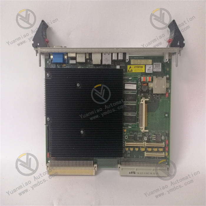
In terms of hardware architecture and system compatibility, the DS200DDTBG1A adopts a "main-standby" dual redundancy hardware architecture. Its core includes two independent signal processing units, 32 digital input channels, 16 digital output channels, a dual power management module, and high-speed redundant backplane interfaces. The two signal processing units synchronously collect and transmit signals; when the main unit fails, the standby unit takes over the work without disturbance, ensuring the continuity of signal acquisition and output. The input channels support two signal types: dry contacts (passive) and wet contacts (active), which can be flexibly configured through the DIP switches on the side of the module to adapt to the signal output needs of different types of sensors. The output channels adopt relay output, with a load driving capacity of AC 250V/5A and DC 30V/5A, supporting direct driving of inductive loads and resistive loads without the need for additional power amplifier modules. In terms of communication, it has built-in dual high-speed backplane bus interfaces, compatible with the proprietary GDS communication protocol of the GE Mark VIe system, enabling 100Mbps signal interaction with the controller module. It also supports module-level address coding settings, facilitating address identification and signal routing during multi-module networking. Relying on industrial-grade reinforced design, the module uses wide-temperature-tolerant components (-40℃~70℃), an enhanced electromagnetic shielding enclosure (complying with IEC 61000-4-2/3/4/6 standards), and an anti-vibration plug-in structure. It can operate stably in industrial sites with high temperature, high humidity, strong electromagnetic interference, and high vibration, meeting the extreme reliability requirements of large-scale units for I/O modules.
The DS200DDTBG1A adopts a "main-standby" dual redundancy hardware architecture, integrating two independent signal processing units, two groups of A/B redundant backplane bus interfaces, and dual redundant power input channels. The two signal processing units synchronously receive on-site input signals and upload them to the controller via the redundant bus, while simultaneously receiving commands from the controller and driving the actions of output channels. It has a built-in redundancy arbitration mechanism that real-time monitors the signal transmission status of A/B channels. When the main channel (e.g., Channel A) experiences signal loss, transmission errors, or hardware failures, the standby channel (Channel B) takes over all signal processing and transmission work without disturbance within ≤1ms, ensuring no loss of input signals and no interruption of output commands. The power input adopts dual independent DC 24V power supplies; when the main power supply fails, the standby power supply is automatically activated with a switching time of ≤1ms, ensuring stable power supply to the core circuit of the module. This full-link redundancy design enables the module to fully meet the reliability requirements of "safety-level" I/O control for large-scale units in fields such as electric power and petrochemicals, with fault tolerance reaching the IEC 61000-4-2/3/4/6 standard.
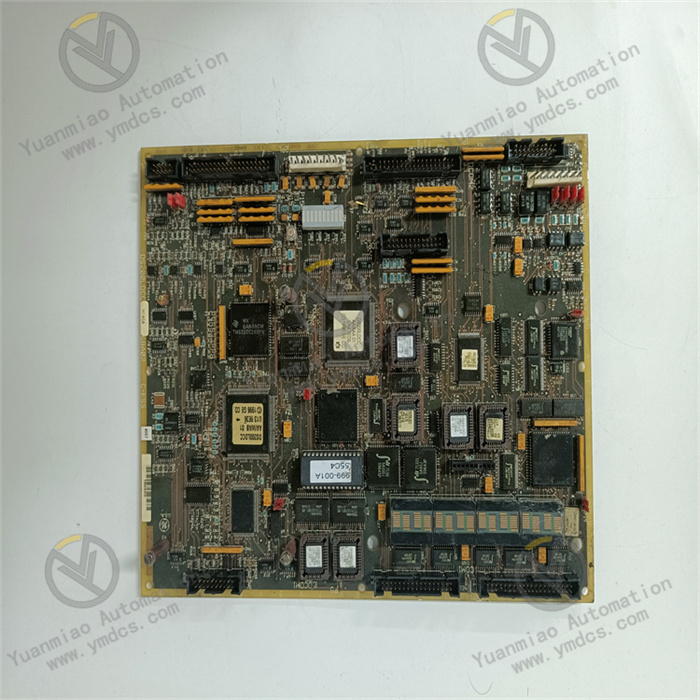
The module integrates 32 digital input channels and 16 digital output channels, adopting a grouped design (4 groups for input, 2 groups for output). Each group of channels can be independently configured with parameters to achieve classified acquisition and control of different types of signals. The input channels support flexible switching between dry contact and wet contact signal types; each group of 8 input channels can be uniformly configured via the DIP switches on the side of the module: when connecting passive sensors such as travel switches and limit switches, it is configured to dry contact mode, using the module's internal power supply to provide detection current; when connecting sensors with active output, it is configured to wet contact mode, directly collecting DC 24V signals provided by the external power supply. The output channels adopt Single-Pole Double-Throw (SPDT) relay output; each channel can control two different executive mechanisms simultaneously (e.g., the "normally open" contact controls the solenoid valve, and the "normally closed" contact controls the alarm indicator light). With a load driving capacity of AC 250V/5A, it can directly drive medium-power executive mechanisms such as contactors and solenoid valves without the need for additional power amplifiers, reducing system integration costs. The grouped channel design allows the module to adapt to the monitoring needs of multiple independent devices simultaneously. For example, in a gas turbine control system, one group of input channels collects fuel system signals, one group collects lubricating oil system signals, one group of output channels controls the ignition system, and one group controls the cooling system, realizing classified management and independent control of signals.
The module adopts a high-performance digital signal processing chip, with an input channel response time of ≤1ms, which can accurately capture the rapid status changes of on-site equipment (such as circuit breaker opening/closing signals and fault pulse signals) and avoid misjudgment of control logic due to response delay. For example, in a power system, when a generator has an "overvoltage" fault, the module can collect the fault signal and upload it to the controller within 1ms; the controller issues a trip command within 5ms; the module's output channel drives the circuit breaker to act within 5ms. The total time of the entire fault response process is ≤11ms, which is far lower than the industry standard requirement of 50ms. The output channels adopt a high-speed relay drive circuit; the delay from receiving the controller's command to the relay contact action is ≤5ms, supporting high-frequency command output (maximum action frequency of 100 times per minute), which is suitable for control scenarios requiring rapid switching (such as the start-stop control of distributors in the metallurgical industry). The backplane bus adopts a 100Mbps high-speed full-duplex transmission protocol; the transmission delay of input signals uploaded to the controller is ≤2ms, and the delay of controller commands issued to the module is ≤2ms, realizing high-speed interaction between I/O signals and the core control unit and ensuring the real-time performance of the control system.
The module has a built-in high-precision fault diagnosis unit, adopting a triple diagnosis mechanism of "hardware self-test + signal verification + communication diagnosis". It can real-time monitor various faults such as input channel open/short circuit, output relay sticking/burning, abnormal power supply voltage, and bus communication failure, with a diagnosis coverage rate of 99.5%. When a fault is detected, it immediately uploads the fault information (including fault channel number, fault type, and fault occurrence time) to the controller and Human-Machine Interface (HMI) via the redundant bus, while lighting up the LED fault indicator lights on the front of the module (red indicator for input faults, yellow for output faults, and orange for communication faults) and generating standardized fault codes (e.g., "IN05: Short circuit of the 5th input channel", "OUT03: Sticking of the 3rd output relay"). It supports local caching of fault signals, capable of storing the latest 500 fault records; fault data can be exported via configuration software for trend analysis. For example, when the 10th input channel has an open-circuit fault, the module immediately uploads the fault code "IN10: Open circuit", and the HMI displays "Input channel 10 is open; please check the sensor wiring". Operation and maintenance personnel can directly locate the fault point according to the prompt, significantly shortening the troubleshooting time.
The module adopts an industrial-grade reinforced hardware design; the enclosure is made of high-strength aluminum alloy material, with an anti-static and anti-corrosion coating sprayed on the surface, which can resist erosion from dust, oil stains, and chemical gases in industrial sites. The internal components are wide-temperature-tolerant models, capable of stable operation in extreme temperature scenarios from -40℃ alpine environments to 70℃ high-temperature workshops, adapting to outdoor control cabinets, areas near high-temperature metallurgical furnaces, and other extreme temperature scenarios. Its electromagnetic shielding performance complies with IEC 61000-4 series standards, with an enclosure shielding effectiveness of ≥60dB, which can effectively resist strong electromagnetic interference generated by equipment such as generators and frequency converters. The input and output channels have an electrical fast transient burst immunity of ±2kV, avoiding false signal acquisition or false command output caused by interference signals. The wiring terminals adopt a Phoenix plug-in design, with anti-loosening and anti-misplug structures, and a contact resistance of ≤10mΩ, ensuring wiring reliability in long-term vibration environments (vibration resistance meets the IEC 60068-2-6 standard of 10g acceleration). The module adopts a plug-in rack installation, enabling quick replacement through guide rails and a snap-lock mechanism; the replacement time is ≤5 minutes, significantly reducing operation and maintenance downtime.
![]()