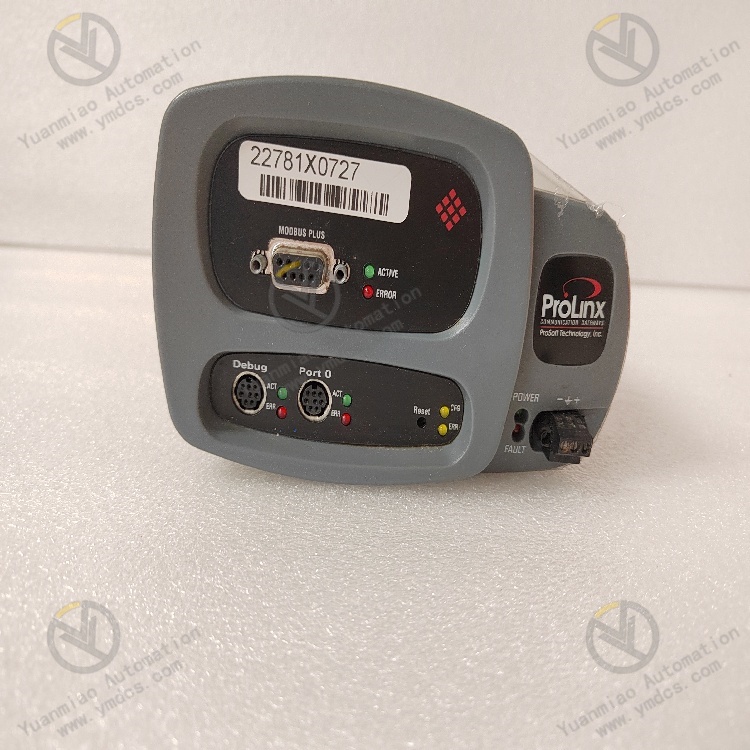
Description
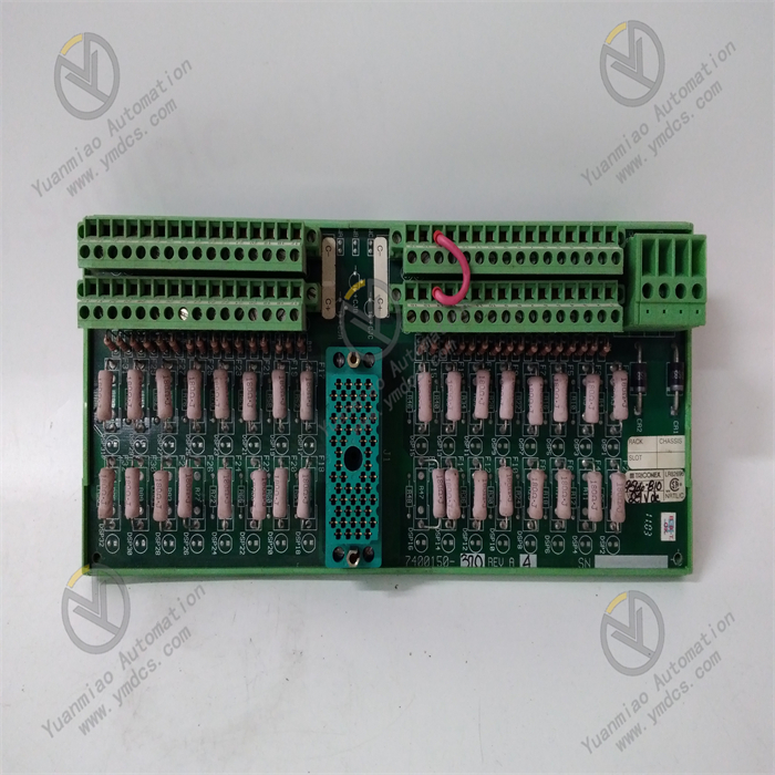
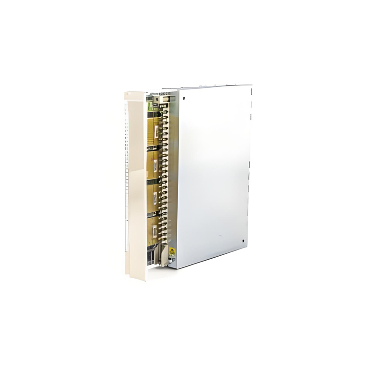
ABB CI615K01 3BSE000756R1
Functional Features: As a bus expansion module, it is primarily used to expand the I/O bus in industrial automation systems, enabling connection and communication between different devices. This allows the system to connect more input/output modules, thereby increasing the number of control points and functional scalability of the system.
Composition Structure: The bus expansion module includes 1 CI615 IOB_A bus coupler for the I/O expansion unit and 1 TC610 bus terminator for the I/O expansion bus.
Technical Parameters: It typically operates at 24VDC, offering high reliability and stability. It can function normally in an ambient temperature range of -20°C to +60°C, supports multiple communication protocols, and is compatible with devices such as ABB's Advant controllers.
Application Scenarios: Widely used in various industrial automation control systems, such as chemical, power, metallurgy, and papermaking industries. In the production process control of these industries, it can expand the system's I/O capabilities to meet the monitoring and control requirements for a large number of devices. For example, in papermaking production lines, it can connect multiple measuring instruments and control devices to achieve precise control and monitoring of various parameters during the papermaking process.
Working Principles:
Communication Principle: As a bus expansion module, it may support multiple communication protocols, such as common industrial Ethernet protocols, to interact data with other devices through specific communication protocols. Taking the MODBUS TCP protocol as an example, it inserts MODBUS application data units into TCP messages to achieve data transmission. It parses received messages to extract valid data and executes corresponding operations based on function codes, such as reading device data or writing data to devices. At the same time, it encapsulates data from local devices according to protocol formats and sends them to other devices, thus enabling communication between devices.
Communication Principle: As a bus expansion module, it may support multiple communication protocols, such as common industrial Ethernet protocols, to interact data with other devices through specific communication protocols. Taking the MODBUS TCP protocol as an example, it inserts MODBUS application data units into TCP messages to achieve data transmission. It parses received messages to extract valid data and executes corresponding operations based on function codes, such as reading device data or writing data to devices. At the same time, it encapsulates data from local devices according to protocol formats and sends them to other devices, thus enabling communication between devices.
Data Processing Principle: Received data may undergo processing such as caching, decoding, and verification. For digital signals, logical judgment and processing may be performed directly; for analog signals, they need to be converted into digital signals through analog-to-digital conversion circuits before processing. Processed data may be stored in internal memory for reading by other modules or devices, or further analyzed and processed according to preset rules (e.g., data calculation, status judgment), followed by corresponding operations based on results, such as controlling relay outputs or sending alarm signals.
Signal Processing Principle: If the module has input signal interfaces, it receives signals from sensors or other devices—for example, digital input signals for receiving binary information and analog input signals for receiving continuous signals (e.g., readings from temperature and pressure sensors). For these input signals, the module performs processing such as sampling, quantization, and encoding to convert them into digital signals that can be transmitted and processed on the internal bus. If the module has output signal interfaces, it generates corresponding output signals based on internal control logic and processing results—for example, digital output signals for controlling the on/off status of external devices and analog output signals for adjusting continuous variables of external devices (e.g., controlling motor speed or valve opening).
Possible Faults and Solutions for ABB CI615K01 3BSE000756R1
I. Power-Related Faults
I. Power-Related Faults
- No Power Supply to Module / Power Indicator Not Lit
- Possible Causes:
- Loose or broken power cord connections.
- Faulty power adapter (e.g., incorrect input voltage, overload protection).
- Damaged internal power circuit of the module (e.g., blown fuse, aged capacitor).
- Solutions:
- Check power cord connections, and re-plug or replace the cable.
- Measure whether the input voltage meets the module's specifications (e.g., 24VDC), and replace the power adapter if necessary.
- If the internal circuit is damaged, contact ABB for repair or module replacement.
- Abnormal Power Indicator (Flashing / Constant Red)
- Possible Causes:
- Unstable power voltage or excessive ripple.
- Internal overload or short circuit in the module.
- Solutions:
- Improve power quality using a voltage stabilizer or filter.
- Disconnect external loads and gradually troubleshoot for short circuits caused by external devices.
II. Communication Faults
- Unable to Communicate with Master Control System
- Possible Causes:
- Poor contact or damage to communication cables (e.g., network cables, bus cables).
- Incorrect communication parameter settings (e.g., IP address, baud rate, slave address).
- Damaged communication interface of the master control system or module.
- Mismatched communication protocols (e.g., incorrect protocol enabled or protocol configuration errors).
- Solutions:
- Check cable connections and test cable continuity with a cable tester.
- Ensure communication parameters of the module match those of the master control system (e.g., Modbus address, Profinet device name).
- Try replacing the communication interface or using a backup port (if available).
- Reconfigure the communication protocol to ensure matching protocol types and data formats (e.g., parity, stop bits).
- Data Loss or Errors in Communication
- Possible Causes:
- Signal instability due to electromagnetic interference (e.g., near motors, frequency converters).
- Excessively high communication rate or cable length exceeding specification limits.
- Outdated module firmware with compatibility issues.
- Solutions:
- Use shielded cables and proper grounding, and keep away from interference sources.
- Reduce the communication rate or shorten the cable length to meet protocol requirements (e.g., maximum cable length for Modbus RTU).
- Upgrade the module firmware to the latest version (refer to ABB's official guidelines).
III. Abnormal I/O Expansion Function
- Unable to Recognize Expanded I/O Modules
- Possible Causes:
- Incorrect connection or poor contact of the I/O bus cable.
- Address conflicts in expanded modules (e.g., multiple modules using the same slave address).
- Inadequate power supply to the module (expanded modules not separately powered or insufficient power capacity).
- Solutions:
- Check bus cable connections to ensure secure terminals and correct polarity.
- Reset the addresses of expanded modules to ensure uniqueness and compliance with the master control system's allowable range.
- Provide independent and stable power to expanded modules, ensuring total power consumption does not exceed the power supply capacity.
- Abnormal Input/Output Signals
- Possible Causes:
- Input signals exceeding the module's range (e.g., analog input overload).
- Output load short circuit or overload, triggering module protection.
- Loose or oxidized terminal blocks with poor contact.
- Solutions:
- Check input signal sources (e.g., sensors) for normality, and adjust the range or replace the sensor.
- Disconnect the load and test the output; if a short circuit is found, troubleshoot the load-side fault.
- Clean and re-tighten terminal blocks, and replace terminals if necessary.
IV. Environment-Related Faults
- Module Overheating or Temperature Alarm
- Possible Causes:
- Poor ventilation in the installation environment, blocked cooling vents.
- Ambient temperature exceeding the module's allowable range (e.g., >60°C).
- Solutions:
- Ensure the module is installed in a well-ventilated location and remove surrounding debris.
- Install cooling fans or air conditioners to reduce the ambient temperature within specified limits
- Faults Caused by Moisture or Dust
- Possible Causes:
- High environmental humidity causing internal circuit short circuits.
- Dust accumulation affecting heat dissipation or contact performance.
- Solutions:
- Use moisture-proof cabinets or sealed enclosures to prevent the module from being exposed to humid environments.
- Regularly clean the module's surface and cooling vents with compressed air to remove dust.
V. Other Common Issues
- Frequent Module Restarts or Freezing
- Possible Causes:
- Firmware defects or program errors.
- Memory overflow (e.g., processing data volume exceeding module capacity).
- Solutions:
- Upgrade the firmware to the latest official version.
- Optimize system configuration to reduce simultaneous tasks or data volume
- Abnormal Indicator Light Status (Non-Power/Communication Related)
- Possible Causes:
- Specific function failures (e.g., redundant configuration anomalies, diagnostic alarms).
- Hardware damage to the module (e.g., FPGA/ASIC chip faults).
- Solutions:
- Refer to the indicator definitions in the module manual to determine the specific fault type (e.g., an ERROR light may indicate a critical fault).
- If hardware damage is suspected, contact ABB for module replacement.