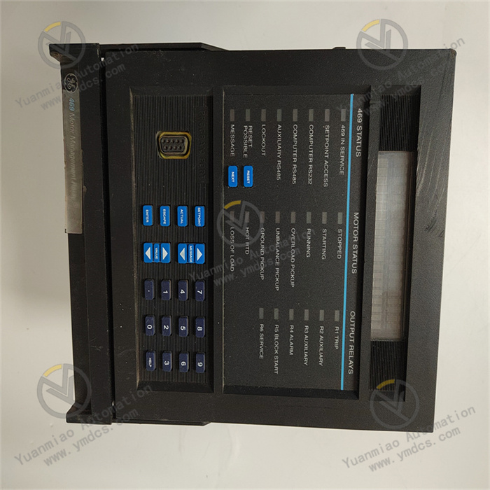
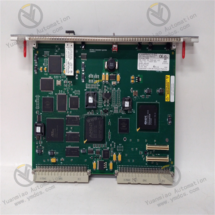
Description
Honeywell 8C-TDODA1 51307149-175
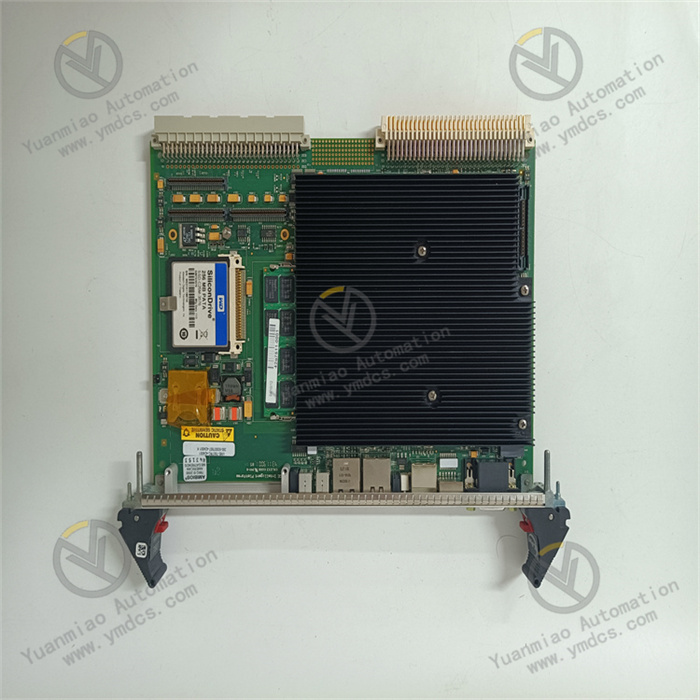
Honeywell 8C-TDODA1 51307149-175 is a digital output connection module used in DCS (Distributed Control System).
Features
Modular Structure:
Designed with a modular architecture, which facilitates quick repair in case of faults. Once a faulty module is identified, it can be rapidly replaced to restore system operation, while also enabling quick troubleshooting.
Designed with a modular architecture, which facilitates quick repair in case of faults. Once a faulty module is identified, it can be rapidly replaced to restore system operation, while also enabling quick troubleshooting.
Hardware Reliability Design:
- Shielding: Key components such as power transformers, CPUs, and programmers are shielded with conductive and magnetically permeable materials to prevent external interference.
- Filtering: Multiple filtering forms (e.g., LC or π-type filter networks) are applied to the power supply system and input lines to eliminate or suppress high-frequency interference and reduce mutual interference between modules.
- Power Regulation and Protection: The +5V power supply required for the microprocessor undergoes multi-stage filtering and adjustment via an integrated voltage regulator to adapt to fluctuations in the AC power grid, overvoltage, and undervoltage.
- Isolation: Optoelectronic isolation is used between the microprocessor and I/O circuits to effectively decouple the electrical connection between the I/O interface and the CPU, reducing faults and misoperations. Additionally, each I/O port is isolated from others.
Software Protection Functions:
- Fault Detection: The software periodically monitors the external environment (e.g., power failure, undervoltage, low lithium battery voltage, and strong interference signals) to enable timely handling.
- Information Protection and Recovery: Occasional fault conditions do not corrupt internal information in the PLC. Once the fault is resolved, the system resumes normal operation and continues the original program. When a fault is detected, the current state is immediately saved to memory, and the software locks the memory to prohibit any operations that could overwrite stored information.
- Watchdog Timer (WDT): If the program execution time per cycle exceeds the WDT-specified time, indicating a potential infinite loop, the system immediately triggers an alarm.
- Program Inspection and Verification: The system alarms and stops execution immediately if program errors are detected.
- Battery Backup for Programs and Dynamic Data: In the event of a power outage, a backup battery preserves the state and information to prevent loss.
Technical Parameters
- Output Type: Digital, field-insulated, bus output
- Number of Channels: 32 channels
- Rated Voltage: 24VDC
- Module Rated Current: 105mA
- Charge Voltage: Maximum 30VDC
- Charge Current: 100mA per channel (max.), 3.2A per module (max.)
- Electrical Isolation: 1000VAC RMS or ±1500VDC
- Operating Temperature: 0°C to 60°C
- Storage Temperature: -40°C to 85°C
- Switching Time: Maximum 10ms
- Dimensions: 22.1cm × 12.1cm × 6.3cm
- Weight: Approximately 0.35kg
Working Principle
- Receiving Control Signals:
The module connects to the controller in the DCS system and receives control commands in digital signal form. These commands are based on the system’s control logic and set values, instructing the module to perform operations such as turning on/off devices or adjusting their operating states. - Signal Processing and Conversion:
Upon receiving digital signals, the module processes and converts them into a format suitable for driving external devices. For example, logic level signals may be converted into signals with specific voltage and current to meet the input requirements of external devices. - Driving External Devices:
The processed and converted signals are sent to external devices (e.g., relays, contactors, indicator lights) to drive them to perform corresponding actions. By controlling the on/off or state changes of external devices, it enables regulation of various physical quantities in industrial processes (e.g., flow, pressure, temperature). - Fault Detection and Diagnosis:
The module has built-in fault detection and diagnosis functions, monitoring its own operating status (e.g., power supply integrity, signal transmission stability). If a fault is detected, the module sends a fault signal to the DCS system via a specific mechanism, allowing the system to take timely actions (e.g., issuing alarms, switching to backup devices, or executing preset fault-handling procedures). - Communication and Coordination:
As part of the DCS system, the 8C-TDODA1 module communicates with other modules and devices to achieve coordinated operation. It can exchange data with controllers, other I/O modules, and supervisory control systems to ensure the overall coordination of the system and enable comprehensive monitoring and optimization of industrial production processes.
Common Faults and Solutions
Abnormal Output Signals
- Symptom: The module’s digital output signals fail to drive external devices (e.g., relays not activating, indicator lights not lighting).
- Possible Causes: Damaged output channels, wiring errors, faulty external devices, incorrect module configuration.
- Solutions:
- Check for hardware damage in output channels (e.g., overheated chips, shorted pins) and replace the module if needed.
- Verify wiring against the schematic, including power supply, signals, and grounding.
- Test external devices (e.g., check for burned relay coils or damaged indicator lights).
- Review module configuration parameters (e.g., output mode, signal type) for compatibility with the application.
Communication Failures
- Symptom: The module cannot communicate normally with the control system or other devices, leading to interrupted or erroneous data transmission.
- Possible Causes: Damaged communication interfaces, mismatched communication protocols, network connection issues, outdated module firmware.
- Solutions:
- Inspect physical connections of communication interfaces for looseness, oxidation, or damage; repair or replace as needed.
- Ensure the module’s communication protocol settings (e.g., baud rate, data bits, stop bits, parity) match those of the control system or other devices.
- Check network devices (e.g., switches, routers) and network cabling for functionality and connectivity.
- Download and install the latest module firmware from Honeywell’s official website to address potential compatibility issues.
Power Supply Failures
- Symptom: No power indicator light, or sudden power loss during operation, rendering the module inoperative.
- Possible Causes: External power supply failure, damaged power module, loose power connections.
- Solutions:
- Use a multimeter to measure the external power supply voltage and ensure it falls within the module’s rated range.
- Check the power module for overheating, unusual odors, or component damage; replace if faulty.
- Tighten loose power connections and ensure secure contact.
Module Overheating
- Symptom: Excessive temperature during operation, possibly triggering overheat protection.
- Possible Causes: Poor heat dissipation, overloaded operation, high ambient temperature.
- Solutions:
- Ensure the module is installed in a well-ventilated location, away from other heat-generating devices.
- Verify that external loads connected to the module are within its rated capacity; reduce load or replace with a higher-capacity module if overloaded.
- Improve the ambient temperature (e.g., install air conditioning or fans) to ensure it stays within the module’s allowable operating range.