Description
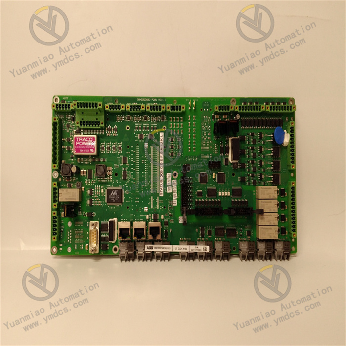
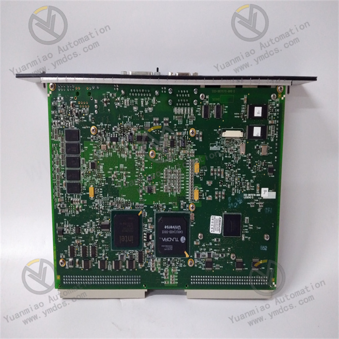
GE IC698CPE030-GJ
The GE IC698CPE030-GJ is a core module of the Programmable Logic Controller (PLC), belonging to the GE 698 Series industrial control hardware system. Specifically designed for standard controller enclosures of the GE 698 Series (such as IC698CHS117C, IC698CHS110C, IC698CHS104C, etc.), it serves as the "computing and control core" of industrial automation control systems.
This product is engineered for medium-to-large-scale discrete manufacturing, process control, and hybrid control scenarios. Its core function is to run preconfigured control programs to perform real-time collection and computational processing of various input signals from industrial sites (e.g., signals from sensors and encoders), and output control commands to drive actuators (e.g., motors, valves, indicator lights). This enables automated control, monitoring, and regulation of production processes. It is compatible with full-specification I/O modules (digital input/output, analog input/output, special-function modules, etc.), communication modules, and power modules of the GE 698 Series. It is widely used in critical industrial fields such as auto parts manufacturing production lines, food and beverage filling lines, building materials processing equipment control, temperature and pressure control of chemical reactors, and water treatment system automation, capable of implementing high-precision and high-reliability control tasks in complex industrial environments.
The IC698CPE030-GJ centers its value proposition on "high-performance computing, multi-protocol communication, high-reliability operation, and flexible expansion." It adopts a 32-bit high-performance embedded processor with a main frequency of 800MHz, equipped with 32MB program memory and 64MB data memory, supporting fast computation of complex control algorithms (e.g., PID, fuzzy control). It integrates mainstream industrial Ethernet communication interfaces such as EtherNet/IP, Modbus TCP, and PROFINET, enabling seamless interconnection with upper-level monitoring systems, other controllers, and intelligent devices. Through industrial-grade hardware design, it features a wide operating temperature range of -20°C to 70°C, 5g vibration resistance, and 15g shock resistance, adapting to harsh industrial conditions. It supports modular expansion, allowing up to 16 I/O module racks to be expanded, meeting the needs of control systems of different scales. Compared with entry-level models in the same series (e.g., IC698CPE020-GJ), the IC698CPE030-GJ delivers significant improvements in computing speed, memory capacity, number of communication interfaces, and expansion capability, enabling it to handle more complex control tasks.
The IC698CPE030-GJ is equipped with a 32-bit high-performance RISC processor with a main frequency of up to 800MHz, combined with 32MB program memory and 64MB data memory, delivering excellent computing and processing capabilities. The execution speed of basic logic instructions is ≤0.1μs/unit, and even complex instructions such as PID calculation and fuzzy control have an execution speed of ≤1μs/unit, enabling fast processing of large-scale I/O data collection and control command output. For example, in an auto parts welding production line, the system needs to simultaneously process 200 channels of digital input signals (e.g., sensor detection signals), 50 channels of analog input signals (e.g., temperature and pressure detection signals), and 100 channels of digital output signals (e.g., welding gun action control). This controller can complete a full cycle of "collection-computation-output" within 10ms, ensuring precise synchronous control of the welding process.
The controller supports multi-task priority scheduling (up to 8 priority levels), allowing flexible allocation of system resources based on control requirements. For instance, in a food and beverage filling line, "accurate filling volume control" can be set as the highest-priority task to ensure real-time response, while "production data statistics" can be set as a low-priority task to run during system idle time. This not only guarantees the real-time performance of core control tasks but also meets data management needs. Meanwhile, the controller has 256 built-in PID loops and supports PID parameter auto-tuning, which can automatically adapt to different controlled objects (e.g., reactor temperature, tank liquid level) without the need for repeated manual debugging. In the scenario of chemical reactor temperature control, the controller can automatically adjust PID parameters based on temperature deviation, stabilizing the temperature control accuracy at ±0.1°C, which is far higher than that of traditional controllers. In addition, the controller supports high-speed counters (max frequency 1MHz, 8 channels) and high-speed pulse output (max frequency 1MHz, 4 channels), enabling high-precision measurement and control of motor speed and conveyor displacement, and adapting to the closed-loop control needs of servo motors and stepping motors.
The IC698CPE030-GJ integrates various mainstream industrial communication interfaces such as EtherNet/IP, PROFINET, Modbus TCP, and RS485, forming comprehensive communication capabilities to achieve seamless interconnection with upper-level computers, other controllers, intelligent devices, and cloud platforms. Among them, the EtherNet/IP interface supports CIP Sync precise time synchronization (IEEE 1588 PTP V2) with synchronization accuracy ≤1μs, enabling precise collaboration in multi-controller distributed control. For example, in a large building materials processing workshop, three IC698CPE030-GJ controllers control the cutting, grinding, and assembly processes respectively. After achieving time synchronization via EtherNet/IP, the action deviation of each process is ≤5μs, significantly improving product processing accuracy.
The PROFINET interface supports IRT real-time communication with a communication cycle ≤1ms, adapting to control scenarios with high real-time requirements (e.g., steel rolling process control in the metallurgical industry). It also supports the Device Level Ring (DLR) function with a ring fault recovery time ≤5ms. Even if a communication node fails, the communication path can be quickly switched to ensure the reliability of the communication link. The Modbus TCP and RS485 interfaces facilitate the integration of legacy equipment, allowing direct connection of sensors, meters, and other devices using the Modbus RTU protocol without additional protocol conversion modules, reducing system upgrade costs. In addition, the controller supports network security functions such as IPsec encrypted communication and IEEE 802.1X authentication, which can effectively prevent unauthorized access and data tampering, ensuring the network security of industrial control systems. This is particularly suitable for smart factory scenarios that require connection to cloud monitoring platforms.
In smart factory construction, this controller can upload real-time production data (e.g., output, pass rate, equipment operation status) to upper-level monitoring systems such as GE Proficy iFIX and Wonderware via EtherNet/IP, enabling visual monitoring of the production process. It can interconnect with servo motors and frequency converters from brands such as Siemens and Schneider via PROFINET to form collaborative control of cross-brand equipment. It can access smart electricity meters and water meters via Modbus TCP to collect and analyze energy consumption data. It can even connect to industrial Internet platforms via EtherNet/IP to enable remote operation and maintenance as well as data analysis. For example, an auto parts factory has built a four-level communication network of "equipment-controller-upper-level computer-cloud" using this controller, allowing managers to view real-time production data of factories worldwide on the cloud and issue production instructions remotely, realizing global production management.
The IC698CPE030-GJ adopts industrial-grade hardware design and craftsmanship, delivering excellent environmental adaptability and reliability for stable operation in harsh industrial environments. In terms of temperature adaptability, the controller has an operating temperature range of -20°C to 70°C, using electronic components with a wide temperature range and an aluminum alloy housing with excellent thermal conductivity. It can operate normally even in outdoor control cabinets in northern winter (-20°C) or high-temperature workshops in southern summer (70°C). When starting at -20°C, the controller can complete initialization and enter the operating state within 3 seconds, with no startup delay or program abnormalities.
In terms of mechanical performance, the controller uses a reinforced PCB design and gold-plated pins, featuring 5g vibration resistance (10~500Hz, 3 axes) and 15g shock resistance (11ms half-sine wave). It can withstand continuous vibration generated by industrial motors and pumps, or shock damage during transportation and installation. In the scenario of rail transit supporting equipment control, the controller is installed in equipment cabinets with severe vibration but still maintains stable computing and communication performance, with no data loss or incorrect output of control commands. In terms of electromagnetic compatibility, the controller has passed EN 55032 Class B and FCC Part 15 Class B electromagnetic emission certifications, as well as EN 61000-4 series electromagnetic immunity certifications. In industrial environments with strong electromagnetic interference (e.g., from industrial frequency converters and high-voltage equipment), it will not radiate interference to affect other devices, nor will it suffer from program abnormalities or communication interruptions due to external interference. For example, in a steel mill's steel rolling workshop, when the controller operates near high-power frequency converters, the communication bit error rate is ≤0.001% and the control command output accuracy is 100%.
In terms of reliability indicators, the controller has an MTBF of ≥300,000 hours and a service life of ≥15 years, far exceeding the industry average. Its program memory uses non-volatile Flash storage, which can retain data for ≥10 years after power-off without the need for a backup battery. It has a built-in hardware watchdog function that can automatically restart the controller within 100ms to resume normal operation when the program enters an infinite loop or other abnormalities occur. In the scenario of unattended water treatment stations, the controller can achieve 24/7 uninterrupted operation throughout the year, with fault downtime ≤2 hours/year, significantly reducing operation and maintenance costs.
The IC698CPE030-GJ has strong expansion capabilities, supporting the expansion of GE 698 Series I/O racks with up to 16 local racks. Each rack can support up to 16 I/O modules, allowing flexible configuration of digital, analog, and special-function modules (e.g., weighing modules, motion control modules) based on the control scale. This adapts to various scenarios from small-scale equipment control to large-scale production line control. For example, in small packaging machine control, only 1 local rack + 8 I/O modules are needed to meet requirements; in large automobile assembly lines, 16 expansion racks + 256 I/O modules can be used to fully cover thousands of control points. Meanwhile, the controller supports remote I/O expansion (via EtherNet/IP or PROFINET) with a maximum of 32 remote I/O nodes, enabling centralized control of equipment distributed in different areas and reducing cable wiring costs.
The controller adopts a dedicated CPU slot design compatible with GE 698 Series enclosures and supports hot-swapping (requires enclosure support). This means that the controller can be directly inserted or removed for replacement or maintenance without shutting down the control system, greatly shortening fault handling time. For example, in the scenario of power auxiliary equipment control, if the controller fails suddenly, maintenance personnel can quickly replace it with a spare controller without interrupting the operation of equipment such as fans and pumps. The system can be restored to operation through fast program download (completing 32MB program download within 10 seconds), avoiding the risk of power supply interruption caused by equipment shutdown. In addition, the controller has a built-in 2.4-inch LCD display that can intuitively show operation status, I/O data, fault codes, and other information. Maintenance personnel can quickly troubleshoot faults without connecting to an upper-level computer. For instance, when the controller has an "undervoltage" fault, the display will directly show the fault code and troubleshooting suggestions, allowing maintenance personnel to locate and resolve the problem within 5 minutes, significantly improving O&M efficiency.
The IC698CPE030-GJ has multiple built-in hardware and software safety protection mechanisms to fully ensure the stability and controllability of the control system. In terms of hardware, the controller is equipped with overvoltage, undervoltage, and overcurrent protection functions. When the input voltage exceeds 28~30V DC (overvoltage) or drops below 18~20V DC (undervoltage), the controller will automatically cut off the power input to prevent damage to the core chip. When the input current exceeds 3A, the overcurrent protection function is triggered to prevent equipment burnout caused by faults such as short circuits. In terms of software, the controller supports program encryption, which restricts program modification and download through password authorization to prevent unauthorized personnel from tampering with the control logic. It also supports program backup and recovery, allowing control programs to be backed up to a USB drive or upper-level computer for quick recovery in case of faults, avoiding production interruptions caused by program loss.
The controller is equipped with comprehensive fault diagnosis and alarm functions, which can real-time monitor its own hardware status (e.g., CPU temperature, memory usage), I/O module status, and communication link status. When a fault occurs, it promptly notifies maintenance personnel through red fault light blinking, fault information display on the LCD screen, and dry contact alarm output (optional). For example, when an analog input module fails, the controller will immediately trigger an alarm, display the faulty module's address and fault type (e.g., signal disconnection), and automatically switch to a backup module (if configured) to ensure the continuity of control tasks. In addition, the controller supports a safe shutdown function, which can quickly cut off output signals according to preset conditions (e.g., emergency stop button activation, critical parameter exceeding limits) to put the equipment in a safe state and avoid safety accidents. In chemical production scenarios, when the reactor pressure exceeds the safety threshold, the controller can trigger a safe shutdown within 10ms, close the feed valve, and activate the pressure relief device to ensure production safety.
- Confirm that the module model is IC698CPE030-GJ, with no external damage, no pin deformation, and no loose interfaces.
- Prepare installation tools (screwdriver, torque wrench, anti-static wristband), insulating tape, power cables meeting specifications (24V DC, 2.5mm² two-core cable), and communication cables (Cat5e shielded twisted pair for EtherNet/IP, dedicated shielded cable for PROFINET).
- Check the installation environment: Operating temperature -20°C ~ 70°C, no corrosive gases, dust concentration ≤1mg/m³, away from high-temperature heat sources (e.g., heaters) and strong electromagnetic interference sources (e.g., frequency converters), with ≥5cm heat dissipation space reserved at the installation location.
- Wear an anti-static wristband and fix the GE 698 Series controller enclosure in the cabinet (the cabinet must be reliably grounded with a grounding resistance ≤1Ω).
- Open the enclosure cover, align the controller with the dedicated CPU slot in the enclosure (usually the first slot on the left), push it in smoothly until a "click" sound is heard, and confirm that the module latch is locked.
- Tighten the fixing screws with a torque wrench to a torque value of 0.8~1.2N·m, ensuring firm contact between the module and the slot.
- Power Cable Connection: Turn off the power, strip the insulation layer of the power cable (approx. 5mm), connect +24V DC (positive) and 0V DC (negative) to the corresponding interfaces of the controller's power terminals respectively, and tighten the terminal screws (torque 0.5~0.8N·m) to ensure no exposed wires. Power cables must be routed separately, away from communication cables to avoid interference.
- Communication Cable Connection: Based on communication requirements, connect EtherNet/IP, PROFINET, and Modbus TCP communication cables to their corresponding interfaces, and tighten the connectors (e.g., ensure RJ45 connectors are locked in place). For RS485 cables, distinguish between A and B lines, connect them to the corresponding terminals correctly, and install a terminal resistor (120Ω) at both ends of the bus.
- Expansion Module Connection: If an expansion rack is configured, connect the main controller to the expansion rack using a dedicated rack connection cable, ensuring a firm connection. Install the I/O modules in the expansion rack and connect the module power and signal cables.
- Check whether the cable connections are correct (no reversed power positive/negative, correct communication wire sequence), whether the terminal screws are tightened, whether the module is installed firmly, and whether the heat dissipation space is sufficient.
- Confirm that the enclosure fan (if equipped) operates normally and that the air outlet is not blocked.
- Check whether the connection between the expansion module and the main controller is normal and whether the module indicator lights show no abnormalities.
- Reconfirm that the power cables, communication cables, and expansion modules are connected correctly, with no short circuits or loose connections.
- Use a multimeter to measure the power voltage, ensuring it is within the range of 21.6~26.4V DC.
- Check whether the communication link between the controller and the upper-level computer is unobstructed and whether the programming software is correctly installed and activated.
- Turn on the controller power and observe the status indicators: The power light (green) stays on for normal power supply; the CPU running light (green) blinks 3 times and then stays on, indicating successful initialization. If the red fault light is on, turn off the power immediately and check the power voltage and module installation.
- View the controller model, firmware version, memory usage, and other information through the LCD screen to confirm consistency with the design.
- Write a control program in GE Proficy Machine Edition software (e.g., write a logic control program using Ladder Diagram), connect to the controller via EtherNet/IP, and download the program to the controller (32MB program download time ≤10s).
- After the download is complete, execute the program verification function to ensure that the downloaded program is consistent with the local program and that there are no transmission errors.
- Configure the I/O modules in the programming software (e.g., set the digital input to PNP or NPN type, set the analog input range to 0~10V DC).
- Execute the I/O scanning function to check whether all I/O modules are recognized normally and whether the module status shows "normal".
- Test the I/O module performance through the forced input/output function: Force a digital input channel to "1" and check whether the input status displayed by the controller is correct; force a digital output channel to "1" and use a multimeter to measure whether the output terminal voltage is 24V DC, ensuring the I/O module works normally.
- Switch the controller to "Run" mode, simulate industrial on-site signals (e.g., input analog signals via a signal generator, manually trigger sensors to input digital signals), and observe whether the controller's output response meets the control logic requirements.
- For example, when debugging PID temperature control logic, set the target temperature to 50°C, change the actual temperature using heating equipment, and observe whether the controller's output signal changes with temperature deviation and whether the temperature stabilizes at the control accuracy of ±0.1°C.
- For sequential control logic, simulate process flow trigger signals, check whether the action sequence of each actuator is correct, and whether the action interval meets the design requirements.
- Test the communication performance of each communication interface:
- EtherNet/IP Interface: Establish communication with the upper-level computer, upload 1000 pieces of real-time data, and check whether the data transmission is complete and without delay.
- PROFINET Interface: Establish communication with the servo motor driver, send pulse control commands, and check whether the motor speed is consistent with the commands.
- Modbus TCP Interface: Establish communication with the smart meter, read the meter's measurement data, and check whether the data reading accuracy is correct.
- Test the Device Level Ring (DLR) function: Disconnect one cable in the ring network and observe whether the controller switches the communication path within 5ms and whether the communication remains normal.
- Simulate common fault scenarios to test the controller's fault diagnosis and alarm functions:
- Simulate power undervoltage (reduce input voltage to 19V DC): The controller should trigger undervoltage protection, the red fault light blinks, and the LCD screen displays the "power undervoltage" fault code.
- Simulate disconnection of an I/O module: The controller should immediately issue an alarm and display the faulty module's address and type.
- Simulate a program infinite loop: The hardware watchdog should trigger the controller to restart within 100ms and resume normal operation.
- Set the controller to "Run" mode and perform a 72-hour continuous loaded operation. Real-time monitor the CPU temperature (should be ≤70°C), memory usage (should be ≤80%), I/O response time (should be ≤10ms), and communication bit error rate (should be ≤0.001%).
- Simulate 2~3 fault scenarios during the period to check fault handling capabilities.
- After the operation, if there are no abnormal alarms and the control accuracy meets the design requirements, confirm that the debugging is qualified and the controller can be put into official operation.
- Daily inspection: Check the controller's operation status (including CPU temperature, memory usage, I/O module status, and communication status) through the LCD screen or upper-level monitoring system every day to ensure no abnormal alarms.
- Weekly inspection: Check the power voltage (21.6~26.4V DC) and whether the cable connections are firm, with no looseness, aging, or heat marks.
- Monthly inspection: Use an infrared thermometer to measure the controller's housing temperature, ensuring it is ≤70°C.
- Quarterly maintenance: Clean dust from the controller surface and heat dissipation holes every quarter (using compressed air for 吹扫,air pressure ≤0.2MPa) to prevent dust accumulation from affecting heat dissipation.
- Semi-annual maintenance: Check whether the communication cable connectors are loose every six months, reinsert and tighten them, and test the stability of the communication link.
- Annual maintenance: Upgrade the controller firmware once a year (download the latest firmware from the GE official website) to improve system performance and security; back up the control program once a year and store it in a USB drive and the cloud to prevent program loss.
- In high-temperature and high-humidity environments (e.g., southern summer workshops), check the controller interior for condensation every month; install a dehumidifier in the cabinet if necessary.
- In dusty environments (e.g., cement production workshops), clean the heat dissipation holes every month and shorten the cleaning cycle to once every 2 weeks.
- In environments with strong electromagnetic interference, check the grounding circuit every quarter to ensure the grounding resistance is ≤1Ω and enhance electromagnetic shielding.
![]()