Description
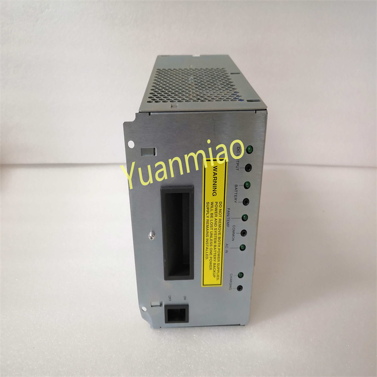
GE IC698PSA100D
I. Overview
GE IC698PSA100D is a high-performance industrial-grade switching power supply module, serving as a core power supply component of the PACSystems RX3i series control systems. Specifically designed to meet the high-reliability power supply requirements of industrial automation control systems, this power supply module acts as the "energy core" of the system, providing stable DC power for RX3i series controllers, I/O modules, and other peripheral devices. It is widely used in industrial fields with strict demands on power supply stability and safety, such as automotive manufacturing, petrochemicals, metallurgical smelting, power energy, and water treatment.
Adopting advanced switching power supply technology and industrial-grade reinforced design, the product features a wide input voltage range, high conversion efficiency, comprehensive protection functions, and excellent anti-interference performance. Its modular structure design enables seamless adaptation to RX3i series racks and supports hot-swapping, facilitating system installation, maintenance, and upgrades. It provides a solid power supply guarantee for the continuous and stable operation of industrial control systems.
II. Technical Parameters
| Parameter Category | Specific Specifications | Description |
|---|---|---|
| Input Parameters | Input voltage: AC 85-264V (wide range); Input frequency: 47-63Hz; Input current: ≤5A (at AC 100V), ≤2.5A (at AC 230V); Power factor: ≥0.9 (full load, AC 100-264V) | Wide voltage input adapts to power grids in different regions; high power factor reduces power grid losses, making it suitable for complex power grid environments |
| Output Parameters | Output voltage: DC 5V; Output current: 20A (rated), 25A (peak, continuous for 10s); Output power: 100W (rated); Output voltage accuracy: ±1% (full load); Ripple and noise: ≤50mVpp | Stable 5V DC output meets the power supply needs of RX3i series modules; peak current adapts to instantaneous load shocks |
| Conversion Efficiency | Typical efficiency: ≥85% (50%-100% load); Full-load efficiency: ≥83% | High conversion efficiency reduces energy consumption, minimizes module heat generation, and improves long-term operational stability |
| Protection Functions | Overcurrent Protection (OCP): 22-25A (adjustable), auto-recovery; Overvoltage Protection (OVP): 5.5-6.0V, output latch; Short-Circuit Protection (SCP): instantaneous current limiting, auto-recovery; Over-temperature Protection (OTP): ≥85℃, auto-shutdown, recovery when temperature drops | Multiple protection mechanisms effectively protect the power supply module and load equipment, reducing fault losses |
| Mechanical & Installation Parameters | Compatible racks: GE PACSystems RX3i series racks; Installation method: rack slot mounting; Hot-swapping: supported (compliant with RX3i system specifications); Dimensions: 101.6mm×160mm×190.5mm (L×W×H); Weight: approx. 1.2kg | Standardized rack adaptation; hot-swapping enhances maintenance convenience; compact structure saves installation space |
| Operating Environment | Operating temperature: 0℃-60℃; Storage temperature: -40℃-85℃; Relative humidity: 5%-95% (no condensation); Protection class: IP20 (module body); EMC resistance: compliant with EN 61000-4-2/3/4/6 standards | Adapts to cabinet-mounted installation environments; strong anti-interference capability ensures stable operation in complex industrial scenarios |
| Monitoring & Indication | Status indicators: Power OK (PWR OK, green), Fault (FAULT, red); Remote monitoring: supports working status feedback via RX3i system bus | Intuitive indicator lights provide operational status feedback; remote monitoring supports centralized system management |
III. Functional Features
- Wide-Range Input and Stable Output: Equipped with a wide AC input design, it can adapt to 85-264V AC voltage, compatible with power grid standards worldwide. Cross-regional applications can be achieved without replacing the power supply module. The output end adopts a high-precision voltage stabilization circuit combined with advanced PWM (Pulse Width Modulation) control technology. This ensures that the output voltage accuracy remains within ±1% and the ripple noise is ≤50mVpp under full load, light load, and load fluctuation conditions, providing pure and stable power supply for sensitive electronic components.
- Multiple Safety Protection Mechanisms: Built-in four core protection functions—overcurrent, overvoltage, short-circuit, and over-temperature—forming a comprehensive safety protection system. Overcurrent protection allows threshold adjustment based on load requirements to avoid false triggering by instantaneous inrush current. Overvoltage protection uses a latching mechanism: when the output voltage rises abnormally, the output is immediately shut down and can only be restored by manual reset, preventing high voltage from damaging load modules. Short-circuit protection responds quickly through instantaneous current limiting technology, and power supply is automatically restored after the short-circuit fault is eliminated, reducing manual intervention. Over-temperature protection monitors the module temperature in real time via a built-in temperature sensor to prevent component damage caused by overheating.
- Hot-Swapping Support and Convenient Maintenance: Strictly compliant with GE RX3i series hot-swapping specifications, the module can be directly plugged in or out while the system is energized. The replacement process does not affect the normal operation of other modules, significantly shortening fault handling time and improving system availability. The module panel is equipped with clear status indicators: the green "PWR OK" light is on when power supply is normal, and the red "FAULT" light is on or flashing when a fault occurs. Combined with remote status feedback via the system bus, maintenance personnel can quickly locate and resolve faults.
- High Reliability and Anti-Interference Design: Uses industrial-grade high-frequency switching power supply chips and reinforced circuit layout. Both input and output ends are equipped with EMC (Electromagnetic Compatibility) filter circuits, which can effectively suppress differential-mode and common-mode interference. Compliant with EN 61000-4 series EMC standards, it can resist the impact of strong interference sources such as frequency converters and motors in industrial sites. The module interior adopts an efficient heat dissipation structure combined with high-temperature-resistant components, ensuring continuous and stable operation in a wide temperature range of 0-60℃, with a Mean Time Between Failures (MTBF) of ≥200,000 hours.
- Energy Efficiency and Environmental Design: With a conversion efficiency of ≥85% in the 50%-100% load range, it saves more than 30% energy compared to traditional linear power supplies, effectively reducing overall system energy consumption and operating costs. The product complies with RoHS environmental standards and uses lead-free soldering technology to reduce environmental pollution. Meanwhile, the low-power design reduces module heat generation, alleviating the burden on the cabinet's heat dissipation system.
- Seamless System Integration Capability: Specifically designed for GE PACSystems RX3i series control systems, it can be directly inserted into the power slot of the RX3i rack. Power distribution and status feedback are realized via the rack bus, eliminating the need for additional wiring and adaptation devices. It supports linkage with the system controller: when the power supply module fails, the controller can promptly receive the fault signal and execute preset redundant switching or alarm logic, improving overall system reliability.
IV. Working Principle
- Input Rectification and Filtering Stage: The AC input power (85-264V AC) first passes through the input EMC filter circuit to remove high-frequency interference and noise from the power grid. It then enters the bridge rectifier circuit to convert AC power into pulsating DC power. The pulsating DC power is filtered by a large-capacity electrolytic capacitor to form a smooth high-voltage DC voltage (approximately 300V DC, varying with input voltage), providing stable input power for the subsequent DC-DC conversion stage.
- DC-DC Conversion Stage: The high-voltage DC voltage is input to the high-frequency switching circuit. The PWM control chip generates high-frequency pulse signals to drive the power switch tube (e.g., MOSFET) to turn on and off alternately, converting the high-voltage DC power into high-frequency pulsating AC power. The high-frequency pulsating AC power is stepped down by a high-frequency transformer to output low-voltage pulsating AC power that meets requirements. This process achieves voltage level conversion and electrical isolation (isolated via transformer windings).
- Output Rectification, Filtering, and Voltage Stabilization Adjustment Stage: The low-voltage pulsating AC power is converted into low-voltage pulsating DC power by a fast-recovery diode rectifier bridge, and then the pulsating components are filtered out by an LC filter circuit (inductor + capacitor) to obtain smooth DC voltage (initial output of approximately 5V DC). To ensure stable output voltage, the module has a built-in voltage feedback circuit that collects the output voltage signal in real time and transmits it to the PWM control chip. The control chip compares the feedback voltage with the reference voltage, adjusts the duty cycle of the pulse signal according to the deviation, and further adjusts the on-time of the power switch tube, stabilizing the output voltage within the range of 5V±1%.
- Protection Monitoring and Status Feedback Stage: During the entire working process, the protection circuit monitors key parameters such as output current, output voltage, and internal module temperature in real time: when the output current exceeds the overcurrent protection threshold, the current detection circuit triggers the PWM control chip to reduce the output pulse duty cycle and limit the output current; when the output voltage exceeds the overvoltage protection threshold, the voltage detection circuit immediately triggers the PWM control chip to shut down the output and lock the protection state; when the internal module temperature exceeds the over-temperature protection threshold, the temperature sensor sends a signal, and the control chip shuts down the output, which automatically recovers when the temperature drops. Meanwhile, the status indication circuit drives the panel LED indicators according to the power supply working status: the green light is on for normal power supply, and the red light is on for faults. Fault information can also be fed back to the system controller via the rack bus.
- Hot-Swapping Control Stage: The module is equipped with a hot-swapping control circuit. When the module is inserted into the rack, the circuit first connects the input power slowly to avoid instantaneous inrush current; at the same time, it communicates with the system via the rack bus to confirm the module model and compatibility before fully connecting the output power to supply power to the load. When the module is pulled out, the circuit first cuts off the output power and then disconnects the input power, ensuring that the plugging and unplugging process does not affect the normal operation of other parts of the system.
V. Common Faults & Solutions
| Fault Phenomenon | Possible Causes | Solutions |
|---|---|---|
| After inserting the module into the rack, the PWR OK light is off and there is no output voltage | 1. Input power not connected or abnormal voltage; 2. Module not properly inserted into the rack, poor contact; 3. Faulty rack power slot; 4. Faulty internal input circuit or PWM control chip of the module | 1. Check the AC input power to ensure the voltage is within 85-264V and the power switch is closed; 2. Power off, reinsert the module to ensure it is fully inserted and locked, check if the rack slot contacts are oxidized, and clean with alcohol; 3. Insert the module into another normal rack slot for testing; if normal, replace the original rack or repair the slot; 4. If the above operations are ineffective, contact GE after-sales to inspect the module's internal circuit |
| PWR OK light flashes, output voltage is unstable | 1. Excessive input voltage fluctuation or severe power grid interference; 2. Overloaded or unstable output load; 3. Aging and failure of output filter capacitor; 4. Faulty voltage feedback circuit | 1. Use a multimeter to measure the input voltage, confirm the fluctuation range is ≤±10%; if the fluctuation is excessive, add a voltage stabilizer; check if the input line is away from interference sources, and add an input filter if necessary; 2. Check the total load current to ensure it does not exceed the 20A rated value, and eliminate load short-circuit or instantaneous overload; 3. Contact professionals to inspect the output filter capacitor and replace aging capacitors; 4. Contact GE after-sales to inspect the voltage feedback circuit and PWM control chip |
| FAULT light is on, no output (overvoltage protection triggered) | 1. Short-circuit or severe overload at the output end; 2. Faulty output voltage stabilization circuit (e.g., deteriorated feedback resistor); 3. Faulty PWM control chip causing excessive output voltage; 4. Faulty internal load module causing abnormal voltage | 1. Disconnect the connection between the module output end and the load, power on the module alone; if the FAULT light goes out, the load is short-circuited or overloaded, so troubleshoot the load fault; 2. Contact professionals to inspect components such as feedback resistors and reference voltage sources in the output voltage stabilization circuit, and replace faulty components; 3. Contact GE after-sales to inspect or replace the PWM control chip; 4. Troubleshoot load modules one by one and replace faulty ones |
| Severe module heat generation, FAULT light flashes intermittently (over-temperature protection triggered) | 1. Ambient temperature exceeds 60℃; 2. Poor cabinet ventilation or faulty cooling fan; 3. Module load is long-term near or exceeds the rated value; 4. Excessive dust accumulation on internal heat sinks or blocked heat dissipation channels | 1. Measure the temperature inside the cabinet to ensure it does not exceed 60℃; if the ambient temperature is too high, add air conditioning or ventilation equipment; 2. Inspect the cabinet cooling fan, replace faulty fans, and clean fan dust; 3. Reduce the load current to ensure long-term operating load ≤16A (80% of rated load); if necessary, add parallel power supply modules; 4. Power off, disassemble the module, clean dust on heat sinks, and ensure unobstructed heat dissipation channels |
| Instantaneous system fluctuation or module damage during hot-swapping | 1. Non-compliance with hot-swapping specifications (e.g., too fast plugging/unplugging); 2. Faulty rack hot-swapping control circuit; 3. Damaged module hot-swapping circuit; 4. Hot-swapping performed when the system load is at full capacity | 1. Strictly follow the operation manual for hot-swapping; plug and unplug slowly and steadily to ensure full contact between the module and the rack; 2. Replace the rack for testing; if the problem persists, repair the rack's hot-swapping control circuit; 3. Contact GE after-sales to inspect the module's hot-swapping circuit; 4. Appropriately reduce the system load before hot-swapping to avoid full-load operation |
| Output current fails to reach rated value, load cannot work normally | 1. Input voltage too low (below 85V AC); 2. Aging or degraded performance of power switch tube; 3. Inter-turn short-circuit of high-frequency transformer; 4. Overcurrent protection threshold set too low | 1. Increase the input voltage to above 85V AC to ensure stable input voltage; 2. Contact GE after-sales to inspect the power switch tube and replace aging components; 3. Inspect the high-frequency transformer; if there is a short-circuit, replace the transformer; 4. Contact professionals to recalibrate the overcurrent protection threshold to the standard range (22-25A) |