Description
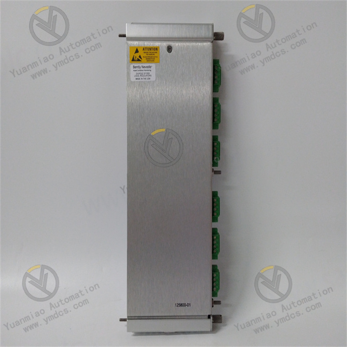
GE Multilin SR745-W3-P5-G5-HI-A-E
I. Overview
The GE Multilin SR745-W3-P5-G5-HI-A-E is an integrated protection relay, focusing on the protection and monitoring of transformers, motors, and distribution lines, and serving as a "safety sentinel" for industrial power networks. Its core function is to capture equipment operating parameters in real time. When faults such as short circuits, overloads, and ground faults occur, it triggers protection actions within milliseconds to cut off the faulty circuit and minimize losses. At the same time, it records fault data to support operation and maintenance work.
With the advantages of "accurate protection + flexible adaptation + stable operation", this device is widely used in scenarios such as transformer protection in chemical parks, motor control in metallurgical workshops, and distribution line monitoring in commercial buildings. It is suitable for both single-machine protection and integration into systems for centralized management and control, making it a cost-effective choice for power safety assurance in small and medium-sized enterprises.
II. Technical Parameters
III. Functional Features
IV. Working Principle
The device operates through a closed-loop process of "collection - judgment - action - recording":First, current/voltage transformers collect on-site signals, which are transmitted to the AD conversion chip after isolation and filtering.The chip converts analog signals into digital signals, and the microprocessor judges the operating status by comparing the signals with preset thresholds.If a fault is detected (e.g., current reaches the short-circuit threshold), it immediately drives the relay to trip and trigger an alarm.At the same time, it records fault information and uploads it to the monitoring system via the communication interface, achieving "rapid fault handling + data traceability".
V. Usage Precautions and Fault Handling
Usage Precautions
Common Faults, Cause Analysis and Solutions