Description
GE Multilin SR469-P5-HI-A20-T-H
I. Overview
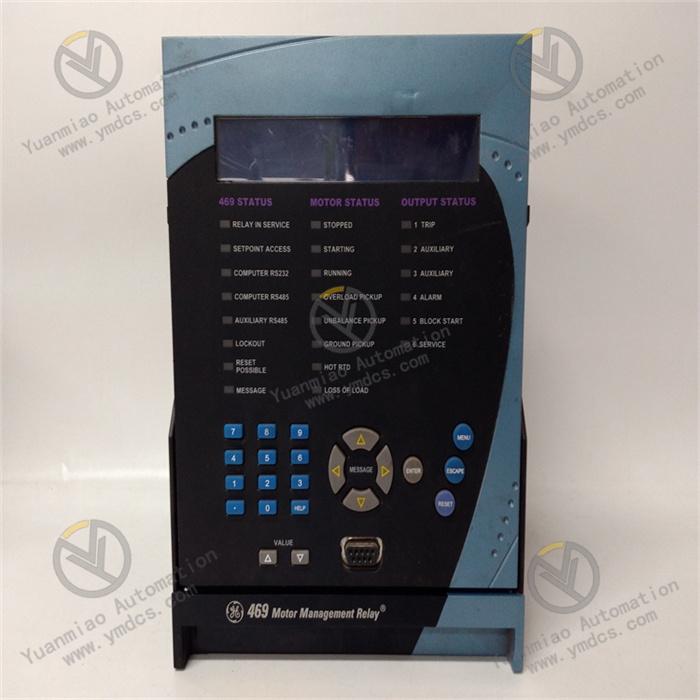
The GE Multilin SR469-P5-HI-A20-T-H is an integrated motor protection and control relay, tailor-made for critical power equipment such as large medium-voltage and high-voltage asynchronous motors and synchronous motors. It integrates four core functions: precise protection, real-time monitoring, logic control, and intelligent communication. Serving as the "core guardian" for motor operation, it not only responds quickly when the motor encounters faults like overload, short circuit, grounding, locked rotor, and overvoltage—cutting off the faulty circuit to prevent equipment damage—but also collects operating parameters in real time and uploads them to the control system. Meanwhile, it supports custom logic control to realize motor start-stop, interlocking, and other operations, providing comprehensive support for the full-life-cycle management of motors.
With its modular configuration, high-reliability algorithms, and wide-scenario adaptability, this device is widely used in industries including electric power, metallurgy, petrochemicals, mining, and cement. It meets the protection and control needs of various large motors such as steel rolling motors, fans, water pumps, and compressors, and is a key equipment in industrial production to ensure the safe and stable operation of motors.
II. Technical Parameters
| Parameter Category | Specification Details | Key Significance |
|---|---|---|
| Electrical Input Parameters | Current input: 0-5A (rated), maximum measurement range 0-60A (20x overload); Voltage input: 0-120V AC (phase voltage), 0-208V AC (line voltage); Frequency measurement: 50/60Hz self-adaptive | Wide-range current input adapts to motors of different capacities, supporting overload condition monitoring. |
| Measurement & Protection Accuracy | Current measurement accuracy ±0.1% FS; Voltage measurement accuracy ±0.1% FS; Power measurement accuracy ±0.2% FS; Protection action accuracy ±0.5%; Action response time ≤10ms (short-circuit protection) | High-precision measurement ensures the accuracy of parameter monitoring, and fast response guarantees timely fault handling. |
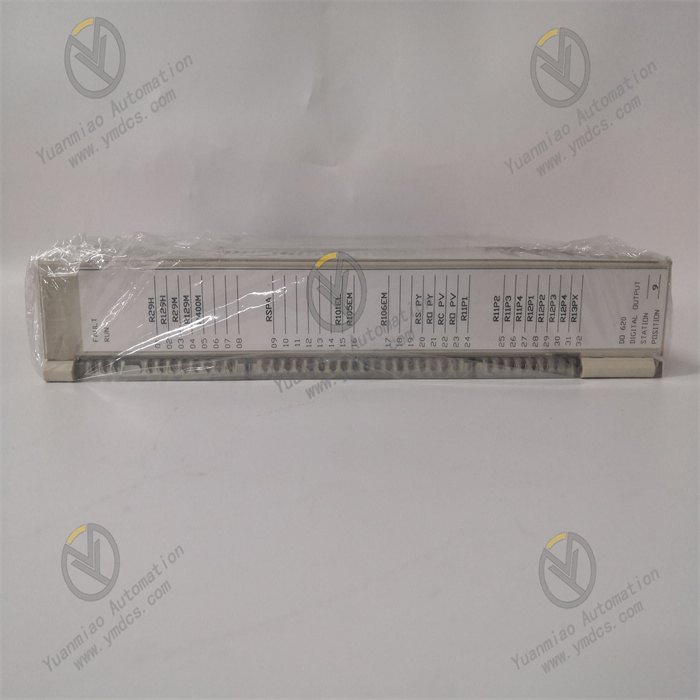
| Output & Control Parameters | Relay output: 8 programmable relays, contact capacity 10A/250V AC, 5A/30V DC; Analog output: 2 channels of 4-20mA, accuracy ±0.1% FS; Digital input: 8 channels of dry contact input | Multi-channel output/input meets complex control needs, and strong contact capacity adapts to various executive equipment. |
| Communication & Power Parameters | Communication protocols: Supports Modbus RTU/TCP, EtherNet/IP, IEC 61850 (optional); Communication interfaces: 1 Ethernet port, 2 RS485 ports; Power input: 85-265V AC/DC, power consumption ≤15W | Multi-protocol and multi-interface adapt to different communication networks, and wide-voltage power supply enhances scenario compatibility. |
| Environmental & Physical Parameters | Operating temperature: -40℃-70℃; Storage temperature: -40℃-85℃; Relative humidity: 5%-95% (no condensation); Protection class: IP20 (panel); Installation method: DIN rail or panel mounting | Wide temperature and humidity design adapts to harsh industrial environments, and flexible installation methods simplify deployment. |
III. Functional Features
- Full-Scenario Motor Protection System: It has a built-in dedicated protection function library for motors, covering more than 20 protection functions such as overload (inverse time/definite time optional), short circuit (instantaneous/short delay), ground fault (residual current/zero-sequence current), locked rotor, phase failure, unbalance, overvoltage, undervoltage, overexcitation, and underload. It supports customizing protection logic, thresholds, and delays via software according to motor type (asynchronous/synchronous) and operating conditions (light load/heavy load, frequent start-stop). For example, it enhances locked rotor and phase failure protection for fan motors with frequent start-stop, and adds excitation fault protection for high-voltage synchronous motors.
- High-Precision Multi-Dimensional Monitoring Capability: Equipped with a 24-bit high-precision AD conversion chip and a high-speed data processing unit, it collects 16 operating parameters in real time, including three-phase current, three-phase voltage, active power, reactive power, power factor, electrical energy, motor speed (requires a speed sensor), and winding temperature (requires PT100). The data update rate reaches 20 times per second, enabling accurate capture of dynamic processes such as motor start-up inrush current and load fluctuations. The built-in data logger can store 500 event records (including fault events and operation events) and 20 waveform records (1 second before and after the fault), with an event timestamp accuracy of 1ms, providing accurate data for fault traceability and root cause analysis.
- Flexible Logic Control & Interlocking: It is equipped with a programmable logic controller (PLC) function, supporting custom control logic through a graphical programming interface to realize motor start-stop, forward-reverse rotation, interlocking control, and standby motor switching—no additional independent PLC is required. For example, an interlocking logic can be programmed as "automatically alarm when the bearing temperature of the fan motor is ≥85℃, and shut down after a 3-second delay and start the standby fan when the temperature is ≥95℃", improving the level of system automation. It supports linkage with other on-site equipment (such as frequency converters and soft starters) to achieve smooth start-up and precise speed control.
- Intelligent Communication & Remote Operation & Maintenance: It supports multiple mainstream industrial communication protocols and can be seamlessly connected to SCADA systems, DCS systems, or industrial Internet platforms, enabling remote monitoring of motor operating parameters, remote configuration of protection settings, and remote push of fault information. Equipped with a web server function, operation and maintenance personnel can access the device interface directly through a browser to view real-time data and download event records without installing dedicated software. It supports device-level redundant communication to improve the reliability of data transmission.
- High Reliability & Fault-Tolerant Design: It adopts industrial-grade high-stability components and an enhanced PCB layout, passes the IEC 61000 series EMC tests, and has strong anti-electromagnetic interference capabilities (ESD ±15kV, surge ±2kV). It has built-in hardware self-inspection and software self-diagnosis functions, which monitor the status of key components such as power supply, AD conversion circuit, relay output, and communication interface in real time. When a fault occurs, it immediately issues a self-inspection alarm and records fault information, while ensuring the normal operation of core protection functions. The modular structure design supports hot swapping of key components (optional), facilitating quick maintenance.
IV. Working Principle
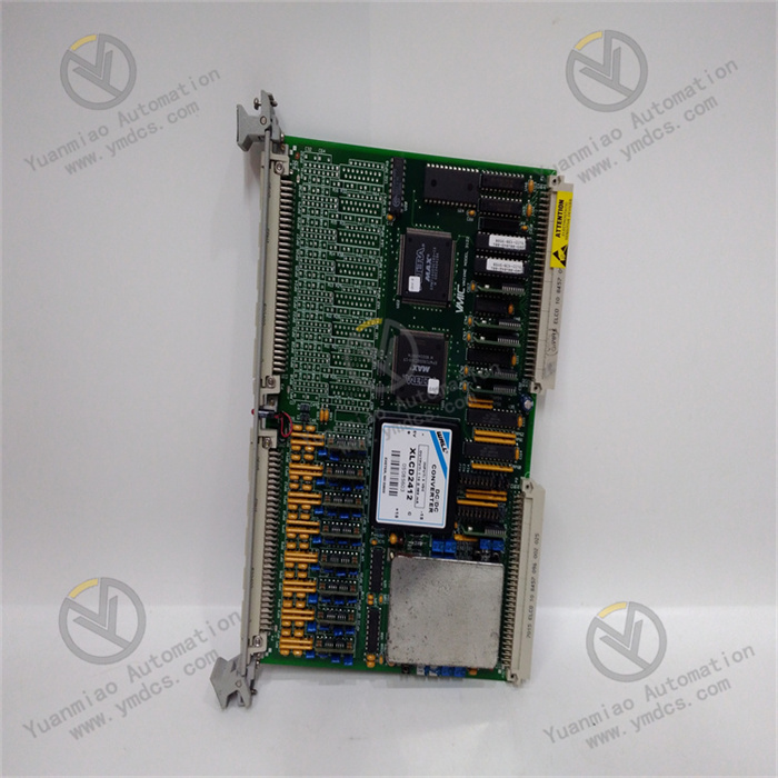
- Signal Collection & Preprocessing: On-site current transformers (CT) and voltage transformers (VT) collect the three-phase current and voltage signals of the motor. These signals are processed for overcurrent and overvoltage protection by the isolation and conditioning circuit (2500V AC optoelectronic isolation) inside the module to filter out high-frequency interference. At the same time, signals such as motor speed and winding temperature collected by the speed sensor and temperature sensor are also connected through corresponding interfaces and preprocessed to ensure stable and reliable input signals.
- Analog-to-Digital Conversion & Data Calculation: The preprocessed analog signals enter the 24-bit high-precision AD conversion chip, which converts them into digital signals and transmits them to the main microprocessor. The microprocessor calls dedicated algorithms to calculate and process the digital signals, deriving real-time operating parameters such as active power, reactive power, power factor, speed, and temperature. These data are stored in the real-time database, and the panel display and communication upload buffer are updated simultaneously.
- Protection Logic Judgment & Control Execution: The microprocessor compares the calculated operating parameters with the preset protection settings (such as overload current threshold and locked rotor time threshold) in real time, and judges the motor operating status based on custom logic. When it detects that parameters exceed the standard (e.g., current reaches the short-circuit threshold) or logic conditions are met (e.g., temperature exceeds the limit), it immediately triggers the corresponding protection action: the relay output module drives the trip relay to act, cutting off the motor power circuit; at the same time, it triggers the alarm relay to send an audible and visual alarm signal. If triggered by control logic (e.g., interlocking to start the standby motor), it drives the corresponding control relay to execute the preset operation.
- Information Recording & Communication Upload: While the action is taking place, the microprocessor immediately records the event type (fault/operation), occurrence time (accurate to ms), and key operating parameters before and after the action. For fault events, it also records the waveform data 1 second before and after the fault synchronously, storing all information in non-volatile memory. Meanwhile, it uploads real-time operating parameters, event records, and device status to the upper-level monitoring system through the communication interface in accordance with preset protocols (such as Modbus TCP) to realize remote monitoring. If it receives control commands from the upper-level system (such as remote start-stop and parameter modification), it executes the corresponding operations after verification.
- Self-Inspection & Fault-Tolerance Guarantee: The main microprocessor runs a self-inspection program simultaneously, regularly verifying the power supply voltage, AD conversion accuracy, relay contact status, and communication links. If it detects that the AD conversion deviation exceeds the standard, it automatically starts the calibration program; if it detects a relay fault, it immediately switches to the standby relay circuit (optional); if it detects a communication fault, it maintains the normal operation of local protection and control functions while issuing a communication fault alarm, ensuring that motor operation is not affected by non-core faults.
V. Common Faults and Solutions
| Fault Phenomenon | Core Cause | Solutions |
|---|---|---|
| No display on the panel and power indicator not lit when the device is powered on | 1. Mismatched input power voltage or unconnected power supply; 2. Loose power terminal connections or broken wires; 3. Faulty internal power module | 1. Check if the power voltage is within the range of 85-265V AC/DC and ensure the power switch is closed; 2. Re-tighten the power terminals, test wire continuity with a multimeter, and replace broken wires; 3. Test with a spare power module and contact after-sales service for repair if the fault is confirmed |
| Frequent false overload alarms during normal motor operation | 1. Overload protection setting is too low; 2. Incorrect current transformer (CT) ratio configuration; 3. Abnormal increase in motor load; 4. Severe interference in current signals | 1. Check the motor rated current and readjust the overload protection setting (usually set to 1.1-1.2 times the rated current); 2. Confirm that the CT ratio is consistent with the configuration in the device and re-enter the ratio parameters; 3. Inspect motor load equipment (such as water pumps and fans) to eliminate jamming, locked rotor, and other issues; 4. Replace with twisted-pair shielded wires, ensure firm wiring on the CT secondary side, and ground the shield layer at one end |
| No trip output after protection action and motor not shutting down | 1. Broken trip relay output circuit or poor contact of contacts; 2. Faulty trip relay; 3. "Trip output" not enabled in the protection logic; 4. Blown fuse in the trip circuit | 1. Power off, inspect the wiring of the trip relay output terminals, re-tighten them, and clean the oxide layer on the contacts; 2. Test the relay output through the device self-inspection function and replace the relay module if the fault is confirmed; 3. Enter the protection logic configuration interface, check and enable the "trip output" function; 4. Inspect the fuse in the trip circuit and replace the damaged one |
| Failure to communicate with the upper-level system and data not uploading | 1. Mismatched communication parameter configurations (address, baud rate, protocol); 2. Broken communication lines or poor contact; 3. Faulty communication interface; 4. Faulty communication node of the upper-level system | 1. Check the communication parameters of the device and the upper-level system to ensure a unique address, consistent baud rate, and matching protocol; 2. Test the continuity of the communication lines with a multimeter and re-tighten the terminals; 3. Replace with a spare communication interface or troubleshoot through the self-inspection function, and replace the communication module if faulty; 4. Inspect the communication nodes of the upper-level system (such as switches and gateways) to eliminate their faults |
| Panel-displayed parameters inconsistent with actual values (e.g., large current display deviation) | 1. Incorrect current/voltage transformer (CT/VT) ratio configuration; 2. Wrong wiring in the signal collection circuit (e.g., reversed current phase sequence); 3. Drifted device measurement accuracy and no calibration; 4. Faulty transformer itself | 1. Recheck the CT/VT ratio and accurately enter the device configuration parameters; 2. Inspect the signal collection wiring and correct phase sequence or wrong connection issues; 3. Calibrate the device accuracy with a standard signal source and adjust the zero point and full scale; 4. Measure the output signal of the transformer and replace the transformer if faulty |