Description
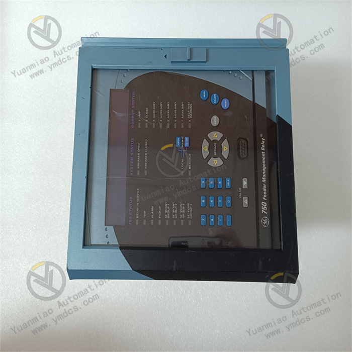
GE Multilin SR750-P5-G5-S5-HI-A20-R-E
The GE Multilin SR750-P5-G5-S5-HI-A20-R-E is an integrated protection relay specifically designed for critical power equipment such as medium and high-voltage motors, transformers, and generators. It combines protection, monitoring, control, and communication functions in one unit. Serving as the "safety guardian" of power systems, it can real-time monitor the operating parameters of equipment. When faults like overload, short circuit, grounding, and overvoltage occur, it quickly triggers protection actions to cut off the faulty circuit. Meanwhile, it uploads fault information via the communication interface, providing comprehensive protection for the safe operation of equipment and operation and maintenance management.
With its flexible configuration, accurate protection algorithms, and stable performance, this device is widely used in fields such as metallurgy, chemical engineering, electric power, and manufacturing. It is suitable for protection scenarios of motors and transformers with different voltage levels, and is an indispensable core device in industrial power systems.
Comprehensive Protection Functions: It has more than ten protection functions including overload, short circuit, ground fault, overvoltage, undervoltage, and locked rotor. The protection logic and parameters can be configured via software according to the equipment type (motor/transformer) to meet the needs of different scenarios. For example, locked rotor protection is enabled for motor protection, and over-excitation protection is enhanced for transformer protection.
High-Precision Monitoring Capability: Equipped with a high-precision AD conversion chip, it real-time monitors three-phase current, voltage, power, power factor and other parameters. The data update rate reaches 10 times per second, which can accurately capture subtle changes in the operating status of equipment and provide data support for fault prediction.
Flexible Communication & Data Management: It supports multiple industrial communication protocols and can be connected to the factory automation system to realize remote monitoring and parameter configuration. It has a built-in data recorder that can store 100 fault records (including fault type, occurrence time, and parameter data), facilitating fault traceability and analysis.
High-Reliability Design: It adopts industrial-grade components and enhanced anti-interference design, passes EMC testing, and can resist electromagnetic interference in industrial sites. It has a built-in self-inspection function that regularly verifies the hardware circuit and software logic to ensure the reliable operation of the device itself.
The device realizes the protection function through a closed-loop process of "signal collection - analysis and judgment - action execution - information upload":First, current transformers and voltage transformers collect the current and voltage signals of on-site equipment, which are transmitted to the AD conversion chip after isolation and conditioning.Second, the chip converts the analog signals into digital signals, and the microprocessor calls the protection algorithm to analyze the data and compare it with the preset protection threshold.If the detected parameters exceed the standard (e.g., current reaches the short-circuit threshold), it immediately triggers the relay output to cut off the faulty circuit.At the same time, it records the fault information and uploads it to the monitoring system via the communication interface, lights up the panel fault indicator, and sends an alarm signal.
During installation, it should be kept away from high-interference equipment such as frequency converters. Ensure the correct polarity of the current and voltage circuits during wiring to avoid equipment damage caused by wrong connection.
Before power-on, check that the power supply voltage is consistent with the rated voltage of the device, and inspect the firmness of the wiring to prevent poor contact caused by looseness.
When configuring parameters, set them accurately according to the rated parameters of the protected equipment (e.g., rated current of the motor) to avoid over-loose or over-strict protection.
Regularly clean the dust on the device surface, check the smoothness of the heat dissipation channel, and prevent high-temperature environments from affecting performance; conduct parameter verification and self-inspection once every six months.
![]()