Description
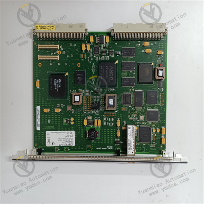
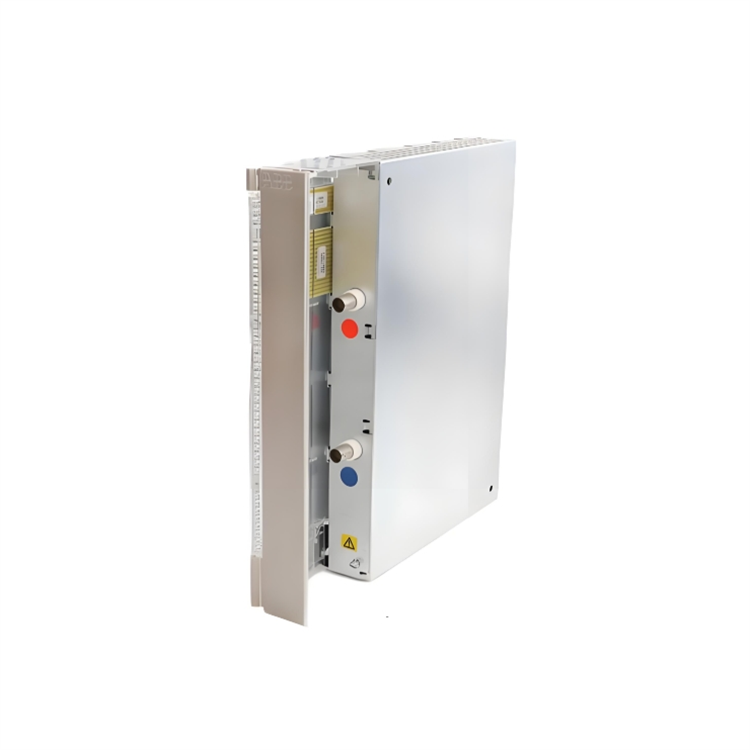
Abaco Systems VMIVME-7807-412010
I. Overview
The Abaco Systems VMIVME-7807-412010 is a high-performance industrial-grade VME bus Single-Board Computer (SBC), part of the VMEbus series of embedded computing products. Specifically designed for harsh industrial environments and mission-critical scenarios, it serves as the core computing unit of control systems, undertaking key functions such as data processing, task scheduling, peripheral management and control, and network communication. This product is widely used in fields with extremely high requirements for computing performance, reliability, and environmental adaptability, including aerospace test equipment, defense electronic systems, industrial automation control stations, medical imaging equipment, and energy monitoring systems.
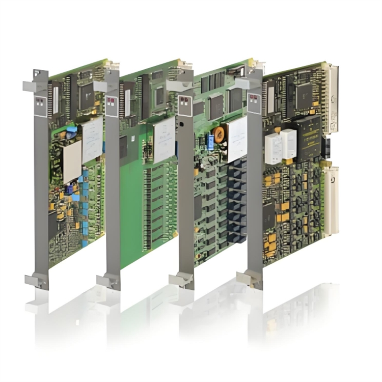
The product adopts an architecture that deeply integrates a high-performance multi-core processor with VME bus technology, featuring powerful computing capabilities, rich peripheral interfaces, and excellent expandability. It strictly complies with the VMEbus 64 standard, enabling seamless integration into existing VME bus systems. Combined with Abaco's customized firmware and software development environment, it supports users in quickly deploying dedicated computing solutions, providing a highly stable and scalable embedded computing platform for complex industrial scenarios and mission-critical tasks.
II. Technical Parameters
| Parameter Category | Specific Specifications | Description |
|---|---|---|
| Core Processor | Processor model: Intel Core i7-6820EQ (4-core, 8-thread); Clock speed: 2.8GHz (max. turbo frequency 3.5GHz); Cache: 8MB L3 cache; Process technology: 14nm; Architecture: Skylake | The high-performance 4-core processor delivers powerful computing capabilities, supporting multi-task parallel processing to meet the requirements of complex algorithm operations |
| Storage System | Memory: Up to 32GB DDR4-2133 ECC SDRAM (2 SO-DIMM slots); Storage interface: 1 SATA III (6Gbps) interface, supporting SSD/HDD; On-board storage: Optional 8GB-64GB eMMC flash memory | ECC memory enhances data storage reliability; the SATA III interface supports high-speed storage devices; on-board eMMC is suitable for high-reliability scenarios without mechanical movement |
| Bus Interface | Bus type: VMEbus 64/32-bit, compatible with VME 1.4 and VME64x standards; Bus speed: Max. 40MB/s in 32-bit mode, max. 80MB/s in 64-bit mode; Bus arbitration: Supports priority arbitration and fair arbitration | The standard VME bus interface ensures compatibility with existing VME systems; high-speed bus transmission meets the data interaction needs of multiple modules |
| Peripheral Interfaces | Network interfaces: 2 Gigabit Ethernet ports (Intel i210, supporting VLAN and TCP/IP acceleration); USB interfaces: 4 USB 3.0 interfaces (2 front, 2 rear); Serial interfaces: 2 selectable RS232/422/485 serial ports; Display interface: 1 HDMI 2.0 interface (supporting 4K resolution); Others: 1 PCIe 3.0 x4 slot, 1 LPC interface | Rich peripheral interfaces adapt to diverse external devices; Gigabit Ethernet supports high-speed network communication; the PCIe slot provides expandability |
| Environmental Parameters | Operating temperature: -40℃ to 70℃ (wide-temperature version); Storage temperature: -55℃ to 85℃; Relative humidity: 5%-95% (no condensation); Vibration resistance: 10-2000Hz, 1.63g (peak-to-peak); Shock resistance: 50g (11ms, half-sine wave); Protection class: IP20 (board-level) | The wide-temperature, vibration and shock-resistant design adapts to harsh industrial environments, meeting the requirements of demanding scenarios such as aerospace and field operations |
| Power Supply & Physical Parameters | Power supply voltage: VME bus power supply (+5V, +12V, -12V); Power consumption: Typical 65W, max. 85W; Dimensions: 233.4mm×160mm (standard 3U VME board); Weight: Approx. 450g | The standard 3U VME board size adapts to VME chassis; multi-voltage power supply ensures stable operation; the power consumption design balances performance and energy efficiency |
| Reliability & Certification | Mean Time Between Failures (MTBF): ≥100,000 hours; Certifications: UL, CE, FCC, EN 61000-6-2/3; Heat dissipation: Conduction + convection cooling, supporting forced air cooling | High MTBF meets the needs of long-cycle operation; multiple certifications adapt to applications in different regions worldwide; efficient heat dissipation ensures stability in wide-temperature environments |
III. Functional Features
- High-Performance Multi-Core Computing Capabilities: Equipped with the Intel Core i7-6820EQ 4-core, 8-thread processor, with a clock speed of 2.8GHz and a maximum turbo frequency of 3.5GHz. Combined with 8MB L3 cache and 14nm process technology, it can efficiently run complex control algorithms, data processing programs, and multi-task operating systems. It supports Intel Hyper-Threading technology, and the 8-thread parallel processing capability improves multi-task scheduling efficiency, meeting the high-performance computing needs of scenarios such as aerospace testing and industrial big data analysis.
- High-Reliability Storage and Memory System: Equipped with 2 SO-DIMM slots, supporting up to 32GB DDR4-2133 ECC SDRAM. ECC (Error-Correcting Code) technology can automatically detect and correct single-bit memory errors, prevent multi-bit errors, and significantly improve data storage reliability, making it suitable for mission-critical data processing scenarios. It provides a dual-storage solution of SATA III high-speed storage interface and on-board eMMC flash memory. The eMMC flash memory has no mechanical moving parts, offering excellent vibration and shock resistance, and is suitable for system booting and data storage in harsh environments.
- Standard VME Bus and Flexible Expansion: Strictly adhering to the VMEbus 64/32-bit standard and compatible with VME 1.4 and VME64x specifications, it can be directly inserted into existing VME chassis and communicate at high speed with other VME modules (such as I/O modules, communication modules, and signal processing modules) via the VME bus. The bus speed reaches 40MB/s in 32-bit mode and increases to 80MB/s in 64-bit mode. The board is equipped with 1 PCIe 3.0 x4 slot and 1 LPC interface, supporting the connection of PCIe expansion cards (such as high-speed acquisition cards and dedicated communication cards) to expand system functions and adapt to personalized application requirements.
- Rich Peripherals and High-Speed Network Communication: Integrated with 2 Intel i210 Gigabit Ethernet controllers, supporting advanced functions such as VLAN, QoS, and TCP/IP checksum offloading, enabling high-speed network data transmission and remote communication to meet the networking needs of distributed control systems. It is equipped with rich peripherals including 4 USB 3.0 interfaces, 2 multi-mode serial ports, and 1 HDMI 2.0 display interface, which can directly connect external devices such as keyboards, mice, monitors, printers, and sensors without additional expansion modules, simplifying system integration.
- Wide-Temperature and Harsh Environment Resistant Design: Adopting wide-temperature components and an enhanced heat dissipation design, the operating temperature range covers -40℃ to 70℃, adapting to industrial scenarios with high temperatures, low temperatures, and severe temperature changes. The board uses a multi-layer PCB design and electromagnetic shielding technology, with vibration resistance of 1.63g at 10-2000Hz and shock resistance of 50g for 11ms, capable of withstanding mechanical stress and electromagnetic interference in scenarios such as aerospace and field operations, ensuring stable equipment operation.
- Comprehensive Software and Firmware Support: Supports mainstream embedded operating systems such as Windows 10 IoT Enterprise and Linux (Ubuntu, Red Hat Enterprise Linux), and provides complete device drivers and Software Development Kit (SDK). The on-board programmable firmware (BIOS/UEFI) supports functions such as boot sequence configuration, hardware diagnosis, and power management, and firmware can be remotely upgraded via the VME bus or network, facilitating system maintenance and function updates. It is equipped with a hardware-level Watchdog Timer (WDT) that can automatically restart the system in case of a system crash, improving system reliability.
IV. Working Principle
- Power Supply and Startup Stage: After the board is inserted into the VME chassis, it obtains +5V, +12V, and -12V power supplies through the VME bus connector. The power management module filters and stabilizes the input voltage to provide stable power supply for components such as the processor, memory, and peripherals. When the user starts the system, the on-board firmware (BIOS/UEFI) executes the Power-On Self-Test (POST) to check the status of hardware such as the processor, memory, storage devices, and bus interfaces. If a fault is detected, fault information is fed back through indicator lights or the bus; after a successful self-test, the operating system is loaded according to the preset boot sequence (booting from eMMC, SATA device, or network).
- System Initialization and Task Scheduling Stage: After the operating system is loaded, it starts the device drivers, initializes peripheral interfaces such as network, USB, serial port, and display, and establishes a Hardware Abstraction Layer (HAL). The processor executes application programs according to system configurations, and allocates CPU resources through the operating system's task scheduling mechanism. The multi-core processor can assign different tasks to different cores for parallel processing—for example, Core 0 runs control programs, Core 1 processes network data, Core 2 performs data operations, and Core 3 is responsible for peripheral management—improving the overall operating efficiency of the system.
- VME Bus Data Interaction Stage: Acting as the master controller or slave device of the VME system, the board communicates with other VME modules through the VME bus interface. When functioning as the master controller, it obtains bus control rights through the bus arbitration mechanism, sends read/write commands to slave modules (such as I/O modules), and reads sensor data, control signals, or writes control commands. When acting as a slave device, it responds to commands from the master controller, uploads its own status data, or executes control commands. The VME bus supports 32-bit/64-bit data transmission, automatically switching transmission modes according to the amount of data. The maximum transmission rate reaches 80MB/s in 64-bit mode, ensuring real-time data interaction between multiple modules.
- Data Processing and Peripheral Management Stage: The processor receives data from channels such as the VME bus, network interface, and serial interface, and executes preset algorithms (such as control algorithms, data filtering algorithms, and image processing algorithms) for data processing. After processing, the results are output through different channels: sent to I/O modules via the VME bus to drive actuators; uploaded to upper-level systems or cloud platforms via Gigabit Ethernet; stored in external storage devices via USB interfaces; and displayed as data visualization results via the HDMI interface. At the same time, the processor monitors the status of peripherals in real time, such as network connection status and storage device read/write status, to ensure the normal operation of peripherals.
- Fault Monitoring and Reliability Assurance Stage: During system operation, the hardware monitoring module collects parameters such as processor temperature, power supply voltage, and fan speed in real time. If parameters exceed thresholds, alarms are triggered through firmware or the operating system—for example, reducing the processor frequency to reduce heat generation or activating backup fans. The Watchdog Timer (WDT) regularly receives a "feed dog" signal sent by the processor. If the system crashes and fails to send the "feed dog" signal, the WDT triggers an automatic system restart to restore normal operation. The VME bus communication process is equipped with a CRC check function, which can detect data transmission errors and request retransmission, ensuring the reliability of data transmission.
V. Common Faults & Solutions
| Fault Phenomenon | Possible Causes | Solutions |
|---|---|---|
| System fails to start, and firmware self-test fails | 1. Abnormal power supply voltage or VME bus power supply fault; 2. Poor contact or fault of the memory module; 3. Fault of the storage device (eMMC/SATA); 4. Fault of the processor or core hardware | 1. Use a multimeter to measure the VME bus power supply voltage, ensure +5V, +12V, and -12V are within the standard range, and check the chassis power module; 2. Power off, reinsert the memory module, and test with a spare memory; 3. Check the storage device detection result through the firmware self-test interface and replace the faulty storage device; 4. If the above operations are ineffective, contact Abaco after-sales service to inspect the core hardware |
| VME bus communication fails, unable to interact with other modules | 1. The board is not fully inserted into the VME slot, resulting in poor contact of the bus connector; 2. Incorrect VME bus arbitration settings; 3. Uninstalled or damaged bus termination resistor; 4. Fault of the VME bus interface | 1. Power off, reinsert the board to ensure the connector is fully connected, and clean the oxide layer on the connector contacts; 2. Check the bus arbitration mode (priority/fair arbitration) through the firmware configuration tool and keep it consistent with other modules in the system; 3. Install 75Ω termination resistors at both ends of the VME bus and replace damaged resistors; 4. Insert the board into another VME chassis for testing, and contact after-sales service for repair if the interface fault is confirmed |
| Network interface fails to connect, data transmission is interrupted | 1. Damaged or poorly connected network cable; 2. Incorrect network configuration (IP address, subnet mask); 3. Abnormal Ethernet controller driver; 4. Hardware fault of the Ethernet controller | 1. Replace the network cable and check the contact of the RJ45 connector; 2. Reconfigure the IP address and subnet mask to ensure matching with the network environment; 3. Uninstall the old driver and install the latest version of the driver; 4. Check the controller status through the operating system device manager, test with a spare network interface, and repair if the fault is confirmed |
| System runs sluggishly, and the processor temperature is too high | 1. Fault of the heat dissipation system (fan stops running, dust accumulation on the heat sink); 2. Excessively high CPU resource occupation by application programs; 3. Abnormal processor frequency settings; 4. Operating environment temperature exceeds the range | 1. Check the fan operation status, clean dust from the heat sink, and replace the faulty fan; 2. Check process resource occupation through Task Manager/top command, optimize or close high-occupation programs; 3. Enter the firmware interface to check the processor frequency settings and restore the default configuration; 4. Measure the operating environment temperature, ensure it is within the range of -40℃ to 70℃, and add heat dissipation equipment if necessary |
| Storage device cannot read/write, data is lost | 1. Poor contact of the storage device interface; 2. Damaged file system of the storage device; 3. Damaged SATA cable (for SATA devices); 4. Hardware fault of the storage device | 1. Power off, reinsert the storage device or SATA cable to ensure good contact; 2. Check and repair file system errors through the operating system disk tool; 3. Replace the SATA cable for testing; 4. If file system repair is ineffective, replace the storage device and restore backup data |
| System crashes frequently or restarts automatically | 1. Unstable power supply voltage or excessive ripple; 2. Memory fault causing data errors; 3. Incorrect Watchdog Timer configuration; 4. Memory leak or deadlock in the application program | 1. Check the VME chassis power module and add a power filter to stabilize the voltage; 2. Replace the ECC memory module for testing and detect the memory through a memory diagnostic tool; 3. Enter the firmware interface to reconfigure the Watchdog Timer parameters (timeout period, restart mode); 4. Debug the application program, troubleshoot memory leak or deadlock issues, and optimize the program code |