Description
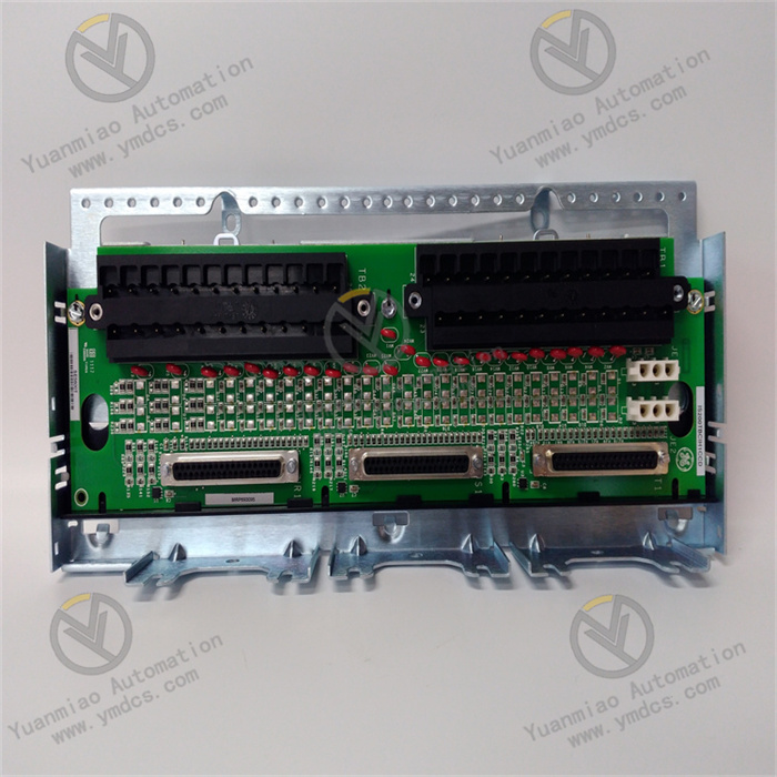
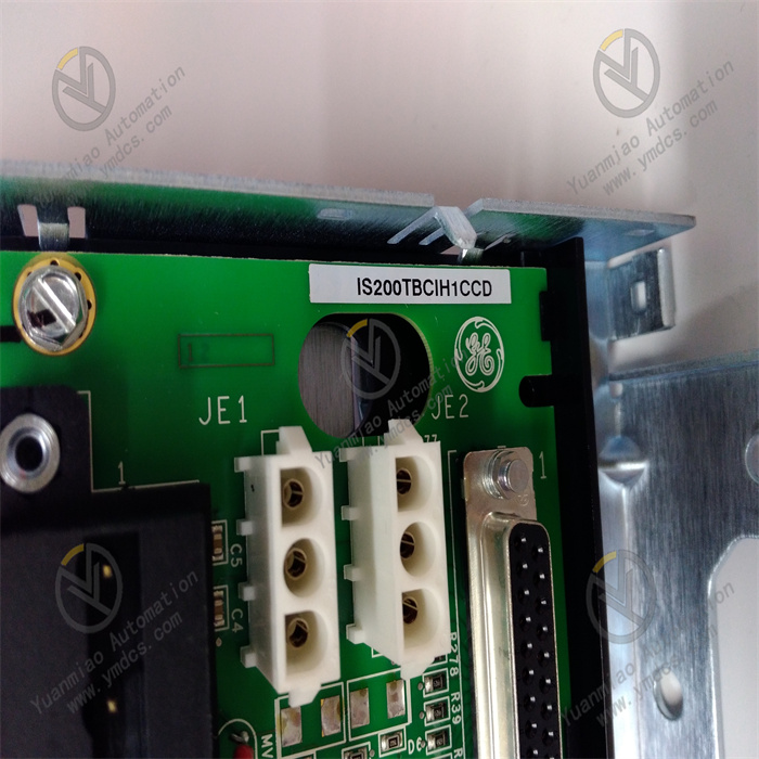
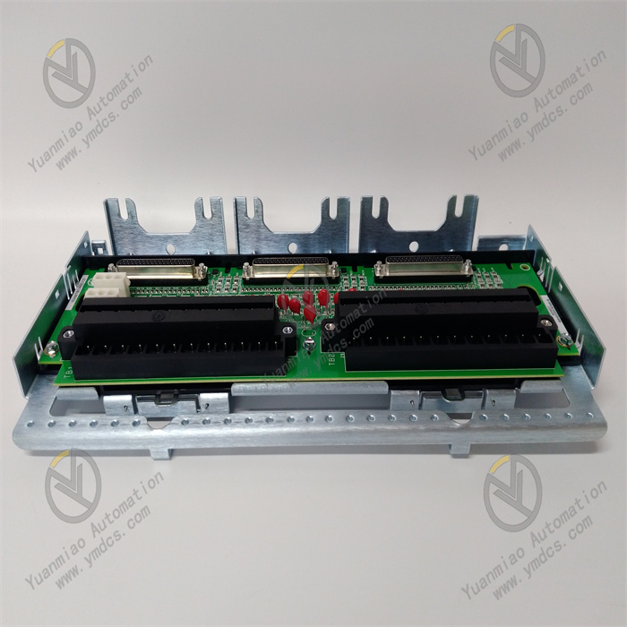
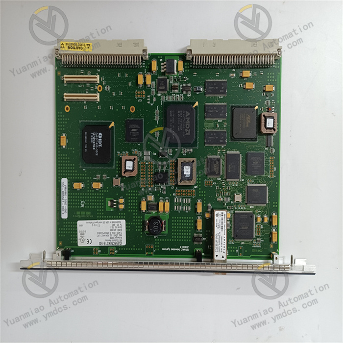
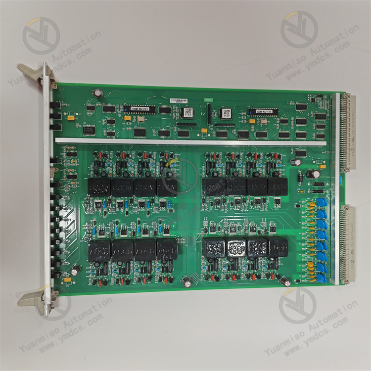
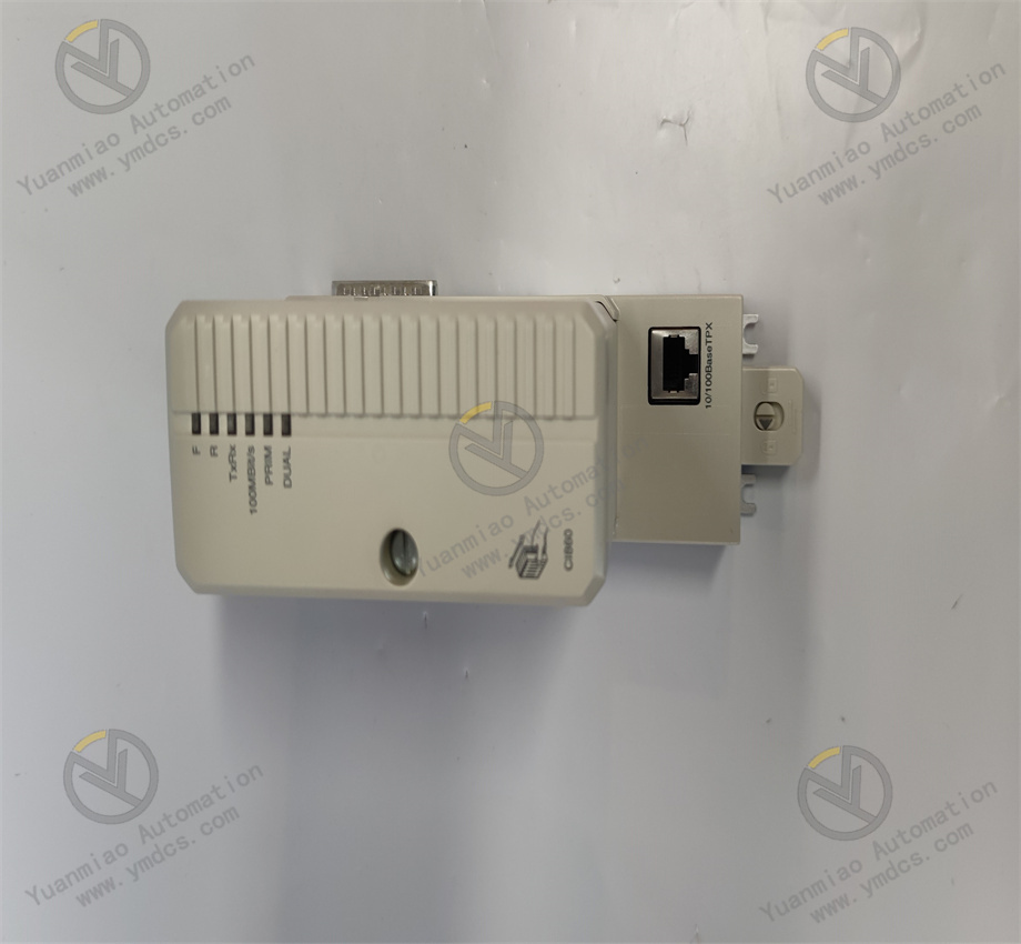
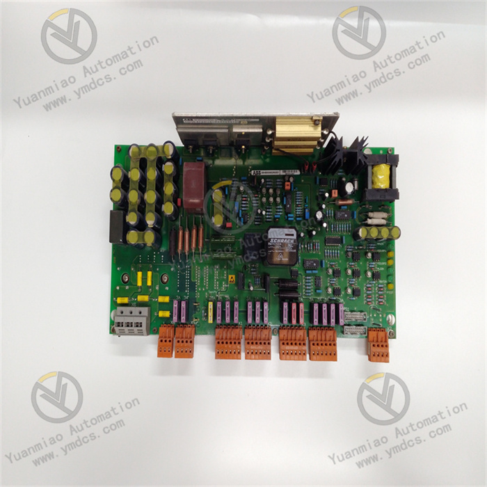
GE IS200TBCIH1CCD
The GE IS200TBCIH1CCD is a control logic and signal processing module belonging to the Mark VIe turbine control system. Its core positioning is a "core unit for executing complex control logic of turbine equipment and conditioning input/output signals". Its core value lies in integrating GE's patented algorithms in the field of turbine control (such as rotor speed PID regulation, load optimization distribution) and high-reliability signal processing technology, providing an integrated solution of "control logic programming and execution + signal filtering and conditioning + redundant control guarantee" for gas turbines and steam turbines.
Compared with general-purpose PLC control modules, it focuses more on "turbine scenario control professionalism" — it supports graphical programming such as Ladder Diagram (LD) and Function Block Diagram (FBD), has a built-in library of turbine-specific control algorithms (such as speed regulation, anti-surge control, overspeed protection), and holds SIL 2 safety certification (IEC 61508) as well as the ability to withstand high vibration (≤5g) and high temperature (ambient temperature ≤65℃). It can operate stably under the harsh working conditions of high electromagnetic interference and high dynamic response requirements of turbines. By collaborating with other modules of the Mark VIe system, it converts signals such as temperature, pressure, and speed collected by I/O modules into control commands (e.g., fuel valve opening adjustment, frequency converter frequency control). When the turbine encounters abnormalities such as overspeed (e.g., speed >3300rpm) or surge, it can trigger emergency control logic within ≤10ms to avoid equipment damage. It is a key control component for "precision control and safe operation" of turbine equipment in industries such as power generation, petrochemicals, and aerospace.
As the core logic execution unit of the Mark VIe control system, this module supports seamless integration with GE turbine controllers (TCIA/TCIB) and HMI, and is compatible with general communication protocols such as Modbus TCP and OPC UA. It balances the professionalism of turbine control and the flexibility of system integration, providing control logic support for "closed-loop control" and "predictive maintenance" of turbine equipment.
- Dedicated Algorithm Library and Fast Response: Built-in turbine speed PID regulation algorithm (regulation accuracy ±0.1% rated speed), anti-surge control algorithm (based on compressor characteristic curve), and overspeed protection algorithm (response time ≤10ms). It eliminates the need for users to develop from scratch, shortening the commissioning cycle of turbine control systems (e.g., reducing the development time of control programs for 300MW gas turbines by 60%).
- SIL 2 Safety Logic Execution: Supports SIL 2-level safety control logic (e.g., "speed >3300rpm → trigger emergency shutdown", "lubricating oil pressure <0.2MPa → cut off fuel supply"). The logic computation adopts a "double verification" mechanism (output after consistent comparison of computation results) to avoid erroneous control caused by a single hardware failure.
- Disturbance-Free Mode Switching: When switching between manual/automatic/remote control modes, a "parameter smooth transition" algorithm is adopted (e.g., when switching from automatic mode to manual mode, the output value remains unchanged to avoid step changes), preventing sudden changes in turbine load or speed (e.g., load fluctuation ≤±1% rated value).
- Full-Type Signal Preprocessing: Analog input supports low-pass filtering (filtering signal noise caused by turbine vibration, with configurable filter coefficient of 0.1-100Hz) and linearization (correcting non-linear errors of pressure transmitters, e.g., correcting 0-1MPa non-linear signals to linear 4-20mA output); digital input supports anti-jitter processing (anti-jitter time 0.1-100ms, avoiding false triggers caused by electromagnetic interference).
- Dedicated Speed Signal Processing: 1 dedicated speed signal interface supports magnetoelectric/photoelectric speed sensors, with a built-in frequency-speed conversion algorithm (e.g., converting 0-10kHz frequency signals to 0-3000rpm speed values). The measurement accuracy is ±0.01% rated speed, meeting the high-precision speed control requirements of turbines.
- Signal Isolation and Protection: Analog/digital input and output all adopt 2.5kVrms photoelectric isolation to avoid module damage caused by turbine equipment leakage or signal crosstalk; analog output is equipped with overcurrent protection (automatic shutdown when >2.5A) to prevent module burnout caused by actuator faults.
- High Vibration and High-Temperature Resistance: The 5g vibration resistance design adapts to mechanical vibration caused by high-speed rotation of turbine rotors; the 0℃-65℃ operating temperature range covers high temperatures in turbine rooms in summer (≤60℃ without air conditioning); logic chips adopt wide-temperature packaging (-40℃-85℃), ensuring no crashes or computation errors in control logic under extreme working conditions.
- Resistance to Strong Electromagnetic Interference: Strong electromagnetic radiation generated by turbine generators and frequency converters can interfere with control signals. The module adopts a three-layer EMC design of "shielding grounding + power filtering + signal isolation", resulting in a logic computation error rate ≤10⁻⁹ (far lower than the industrial requirement of 10⁻⁶), ensuring accurate output of control commands.
- Dual Redundancy Guarantee: Supports dual-module hot redundancy (main and standby modules run synchronously, with real-time synchronization of programs and parameters) and dual-power redundancy (switching time ≤10ms). When the main module or main power supply fails, the standby link switches seamlessly, ensuring uninterrupted turbine control and meeting the turbine safety requirement of "no single point of control failure".
- Visual Programming and Debugging: Control logic is developed graphically via GE ToolboxST software (supporting LD/FBD/ST programming), with built-in turbine control program templates (e.g., gas turbine startup logic, steam turbine load regulation logic). Even non-professional turbine control engineers can complete basic program development within 1 week; it supports online monitoring of program operation status (e.g., viewing PID output values, logic contact status) to quickly locate program bugs.
- Cross-System Integration and Data Interaction: Optional Modbus TCP and OPC UA protocols enable "upload of control program status" (e.g., PID parameters, interlock status uploaded to DCS/HMI) and "download of external commands" (e.g., load target values issued by DCS, remote start/stop commands). It supports connection with the GE Predix cloud platform, uploading control algorithm operation data (e.g., speed regulation deviation) for predictive maintenance.
- Fault Self-Diagnosis and Maintenance: Automatically detects program operation anomalies (e.g., infinite loops, computation overflow), signal conditioning faults (e.g., AI signal out of range), and module power anomalies. Fault information is clearly displayed via LED indicators and HMI (e.g., "PID Output Overflow", "AI Signal Out of Range"), allowing operation and maintenance personnel to quickly locate problems (e.g., checking sensors or modifying programs).
A 300MW gas turbine needs to achieve: 1. Speed control (rated speed 3000rpm, speed rises to 3000rpm during startup, regulation accuracy ±1rpm); 2. Load control (adjust load according to grid demand, from 0MW to 300MW, load change rate ≤5MW/s); 3. Overspeed protection (trigger emergency shutdown when speed >3300rpm). The module is required to operate stably in a gas turbine environment with high vibration (≤3g) and turbine room temperature of 30℃-60℃, and collaborate with other modules of the Mark VIe system to achieve closed-loop control.
- Control Logic Development: Use FBD programming via ToolboxST software, call the built-in "speed PID regulation" algorithm (proportional gain P=2.0, integral time I=5s, derivative time D=0.5s) and "load distribution" algorithm, and construct the control logic of "speed control → load regulation → overspeed protection".
- Signal Processing and Control Output: Receive the speed signal (magnetoelectric sensor, 0-10kHz) collected by the IS200TPROS1CBB module, convert it to a 3000rpm speed value via a dedicated speed processing algorithm; output a 4-20mA command to the fuel valve positioner (to adjust fuel flow) according to the speed deviation, realizing closed-loop speed control; during load regulation, receive the load target value issued by the DCS, and adjust the fuel valve opening and compressor guide vane angle via the load distribution algorithm.
- Safety Protection: When the speed >3300rpm, trigger the SIL 2-level overspeed protection logic, output a DO signal to cut off the fuel valve within ≤10ms, and upload a shutdown command to the controller to avoid gas turbine damage.
A 6MW steam turbine (driving a catalytic fan) in a petrochemical catalytic cracking unit needs to achieve: 1. Anti-surge control (adjust fan speed according to the pressure difference between fan inlet and outlet to avoid surge); 2. Load regulation (adjust fan load according to the demand of the catalytic unit, load range 0-6MW); 3. Lubricating oil pressure interlock (reduce load to 3MW when lubricating oil pressure <0.2MPa). The environment is a catalytic workshop (high dust, strong electromagnetic interference, temperature 25℃-40℃).
- Anti-Surge Logic Execution: Call the built-in "anti-surge control" algorithm, receive the fan inlet pressure (0-0.5MPa) and outlet pressure (0-2MPa) signals collected by the IS200TPROS1CBB module, calculate the pressure ratio (outlet pressure/inlet pressure); when the pressure ratio is lower than the surge line, output an AO signal to adjust the steam turbine speed (increase speed to move away from the surge zone).
- Load and Interlock Control: Receive the load target value (0-6MW) issued by the DCS, adjust the steam inlet valve opening via the PID algorithm (AO 4-20mA to control the valve positioner); when the lubricating oil pressure <0.2MPa, trigger the interlock logic, output a DO signal to reduce the load to 3MW, and upload an alarm to the HMI.
- Anti-Interference and Protection: The module is installed in a sealed control cabinet (IP54); signal cables use shielded twisted pairs (single-end grounding of the shield layer) to resist electromagnetic interference in the catalytic workshop; EMC design ensures no errors in anti-surge logic computation, avoiding fan surge caused by interference.
![]()


