Description
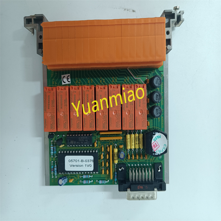
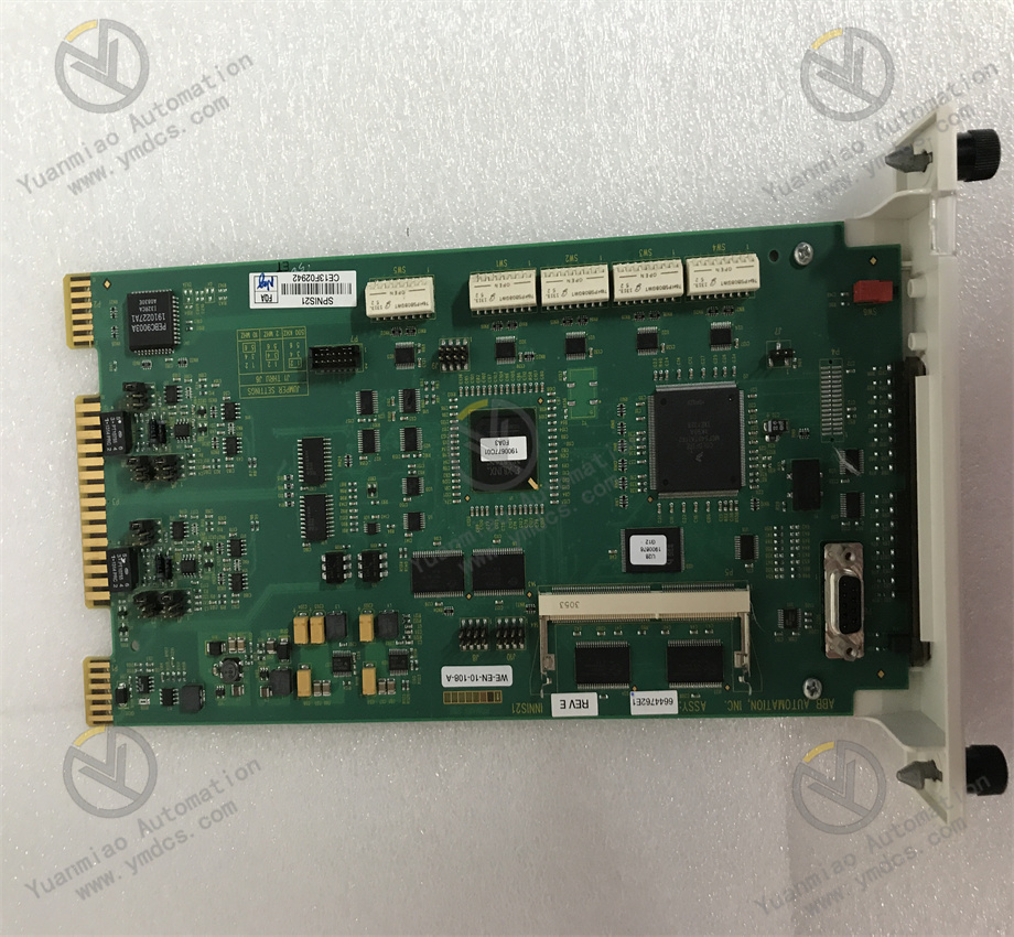
GE IS230SNIDH1A
The GE IS230SNIDH1A is a high-performance industrial-grade digital input/output (I/O) module, which belongs to the core I/O component system of GE's Mark VIe Distributed Control System (DCS) and Speedtronic turbine control system. Its core positioning is to serve as a "bridge" for digital signals in industrial sites, enabling accurate collection of digital inputs such as equipment switch status and alarm signals, as well as reliable control of digital outputs such as actuator start/stop and valve opening/closing. Through its highly stable hardware architecture, flexible channel configuration, and strong system compatibility, it provides core support for the logic control and status monitoring of key industrial equipment such as turbines, generators, and boilers.
The application scenarios of this module extensively cover fields with strict requirements for digital I/O response speed and reliability, including power energy (status monitoring of turbine auxiliary equipment in thermal power units, switch control of generator excitation systems), petroleum and chemical industry (valve switch control of chemical plants, status collection of pump set start/stop), metallurgy and steel (interlock control of rolling production line equipment, status monitoring of blast furnace fans), and heavy manufacturing (control of auxiliary equipment for large machine tools, signal interaction of production line workstations). As a dedicated I/O module for GE's high-end control systems, it can not only efficiently process massive digital signals but also seamlessly collaborate with system controllers, supporting the rapid deployment of complex interlock logic. It is a key hardware component for building highly available industrial logic control systems.
In terms of hardware architecture and system compatibility, the GE IS230SNIDH1A adopts a standardized modular design, which can be seamlessly integrated into the IC695 series I/O racks of the GE Mark VIe control system and Speedtronic turbine control cabinets, occupying one standard I/O module slot. It realizes high-speed data interaction with the system controller through the backplane bus. The module is compatible with GE CIMPLICITY HMI and iFIX monitoring software, supporting the configuration of channel functions, filtering parameters, and alarm logic through a graphical interface, enabling system integration without underlying code development. Relying on its industrial-grade reinforced design, the module has excellent anti-vibration, anti-electromagnetic interference, and wide-temperature adaptability, and can operate stably in complex industrial site conditions with high temperature, dust, and strong interference.
The GE IS230SNIDH1A adopts a high-low channel configuration of 16 inputs + 8 outputs, which can simultaneously meet the needs of massive digital signal collection and centralized control, and is suitable for typical industrial on-site application scenarios of "more monitoring, less control" (such as status monitoring of turbine auxiliary equipment and control of key actuators). The input channels support a standard DC 24V voltage and optional DC 12V/48V configurations, compatible with dry contact (e.g., travel switch) and wet contact (e.g., sensor active signal) inputs, and support one-click PNP/NPN polarity switching. It can adapt to different types of sensors without replacing the module, greatly improving on-site adaptation flexibility. The output channels adopt a transistor-driven method, with a continuous output current of 2A per channel and a peak output current of 5A (within 100ms), which can directly drive small motors, solenoid valves, indicator lights, and other actuators without additional relay amplification, simplifying the design of peripheral circuits.
The response time of the module's input channels can be flexibly configured according to scenarios. The fast response mode with a minimum of 1ms can accurately capture instantaneous fault signals of equipment (e.g., motor overload trip signals), and the filtering mode with 100ms can effectively suppress high-frequency interference in industrial sites (e.g., electromagnetic noise generated by frequency converters), avoiding misjudgments caused by false signals. The output channel response time is ≤100μs, and only microseconds are required from the controller issuing a command to the output state switching, which can meet the real-time requirements of interlock control for high-speed production line equipment (e.g., emergency shutdown control of rolling production lines). The input channels are equipped with built-in RC filter circuits and photoelectric isolation units (isolation voltage ≥2500Vrms), which can effectively filter out common-mode interference and differential-mode interference, ensuring the stability of input signals; the output channels adopt independent drive circuits with no crosstalk between channels, ensuring the accurate output of control signals.
The module has a fault diagnosis coverage rate of 99.8%, integrating full-dimensional diagnosis functions for input, output, power supply, and isolation circuits. The input channels can automatically identify signal open circuits (e.g., sensor wire breakage), short circuits (e.g., signal wire short circuit to ground), and abnormal signal fluctuations; the output channels real-time monitor overcurrent (e.g., actuator short circuit) and overvoltage (e.g., abnormal power supply voltage) faults; the module-level diagnosis can monitor the power supply voltage, backplane communication, and isolation circuit status. When a fault occurs, standardized fault codes are generated immediately (e.g., input channel short circuit code E101, output overcurrent code E203), and hierarchical alarms are issued through local LED indicators (yellow light flashes for input faults, orange light flashes for output faults, and red light stays on for module faults). At the same time, fault information is uploaded to the controller and upper-level system, clearly indicating the fault location and type. The output channels are equipped with built-in overcurrent protection circuits, which automatically cut off the output when overcurrent occurs and resume normal output after the fault is eliminated, avoiding module burnout and actuator damage.
It supports 1:1 module hot redundancy configuration. The master and standby modules realize real-time data synchronization through a dedicated redundant communication link, including input collection data, output status, fault information, and configuration parameters, with a synchronization delay ≤1ms. During normal operation, the master module performs signal collection and output control, while the standby module monitors the status of the master module in real time and synchronizes data; when the master module experiences power failure, communication interruption, or batch channel faults, the standby module automatically switches without disturbance within 10ms and takes over all I/O functions. The output status remains stable during the switching process, ensuring that the control logic of key equipment such as turbines and boilers is not interrupted. The module has channel-level fault isolation capability. When a single channel fails, it is automatically isolated without affecting the normal operation of other channels. In addition, the backup strategy for faulty channels (e.g., automatic switching to redundant channels) can be configured through software, further improving the system's fault tolerance.
The module is compatible with GE CIMPLICITY HMI and iFIX monitoring software, supporting full-parameter configuration through a graphical interface, including input channel filtering time, polarity configuration, alarm thresholds, output channel driving mode (high-side/low-side), overcurrent protection thresholds, and group control logic. No underlying code writing is required, and the configuration efficiency is improved by more than 70% compared with traditional modules. The software has built-in common industry application templates (e.g., turbine auxiliary equipment control template, pump set start/stop control template), which include preset I/O configurations and interlock logic. After import, integration can be completed by only fine-tuning parameters. The module realizes high-speed data interaction with the GE Mark VIe controller through the backplane bus, with a data transmission rate ≥100Mbps, supporting the controller's online diagnosis and parameter modification of the module. Maintenance and debugging can be completed without shutting down the machine, reducing production interruption time. At the same time, it supports the Modbus TCP protocol and can be flexibly integrated into third-party DCS systems, improving the flexibility of cross-brand system integration.
The module adopts an industrial-grade reinforced hardware design. The housing is made of flame-retardant ABS material with an IP20 protection rating, which can effectively resist dust intrusion in industrial sites. The internal circuit uses FR-4 immersion gold PCB boards, and key components are wide-temperature industrial-grade devices (operating temperature: -40℃~85℃), ensuring stable operation in extreme environments such as high-temperature workshops and cold outdoors. It has passed strict mechanical environment tests, capable of withstanding vibration and impact with a frequency of 10~500Hz and an acceleration of 10g, making it suitable for installation near equipment with large vibrations such as turbines and fans. Its electromagnetic interference resistance complies with IEC 61000-4 series standards, with ±25kV air discharge ESD protection, ±4kV surge protection, and ±2kV EFT (Electrical Fast Transient) protection capabilities. It can still ensure the accuracy of signal collection and control in strong interference environments such as frequency converters and high-voltage motors.
The GE IS230SNIDH1A realizes accurate digital I/O processing through the collaboration of hardware circuits and software logic, based on the core workflow of "signal collection - signal processing - logic interaction - output driving - fault diagnosis". The specific working mechanism is as follows:
Digital signals from on-site sensors or switchgear are connected to the module through input terminals and first enter the signal conditioning circuit. According to the configured signal type (dry contact/wet contact), the conditioning circuit automatically switches the power supply mode (dry contacts require the module to provide excitation voltage, while wet contacts directly collect external signals); it adapts to PNP/NPN signals through a polarity switching circuit to ensure correct signal polarity. The conditioned signal is filtered to remove high-frequency interference by the RC filter circuit, and then sent to the photoelectric isolation unit to achieve electrical isolation between the input channel and the module's internal circuit, preventing external high voltage or interference from invading the core circuit. The isolated signal is sent to the level detection unit, converted to a standard TTL level, and then transmitted to the data acquisition unit. The acquisition unit stores the signal state (high/low level) in the input register, and at the same time, the diagnosis circuit monitors the signal amplitude and stability to identify faults such as open circuits and short circuits.
The module establishes high-speed communication with the system controller through the backplane bus. The signal status in the input register is uploaded to the controller at a fixed cycle (minimum 1ms) for the controller to perform interlock logic operations; at the same time, it receives the output control commands issued by the controller and stores them in the output register. The controller can perform logical processing on input signals (such as anti-shake delay and signal interlock) and group control on output commands (such as starting multiple associated actuators simultaneously) through software configuration. In the redundancy configuration mode, the master module synchronizes the input register, output register, and fault status data to the standby module in real time through the redundant link. The standby module verifies the data consistency between the master and standby modules in real time through a comparator to ensure no data difference during switching.
The output driving unit reads the control command from the output register, switches the transistor switch state according to the configured driving mode (PNP/NPN, high-side/low-side), and outputs the corresponding level signal to the actuator. The driving circuit is equipped with a built-in current detection resistor to monitor the output current in real time. When the current exceeds the set threshold (e.g., 2A continuous output threshold), the overcurrent protection circuit is triggered immediately, cutting off the transistor driving signal and sending an overcurrent fault signal to the diagnosis unit. After the overcurrent fault is eliminated, the protection circuit resets automatically and resumes normal output. The output status feedback circuit collects the actual status of the output terminals in real time and compares it with the command status in the output register. If there is an inconsistency (e.g., the command is "on" but there is no actual output), an output fault alarm is triggered immediately.
The master and standby modules exchange health status signals 1000 times per second through the redundant communication link. The master module monitors the communication status and hardware status of the standby module, and the standby module tracks the operating status of the master module in real time. When the master module detects its own fault (e.g., abnormal power supply, backplane communication interruption) or abnormal status of the standby module, it immediately sends a fault report to the controller and requests switching; after the controller confirms, it issues a switching command. The standby module takes over the control right of the backplane bus within 10ms and synchronizes its own output register status to the output driving unit to achieve switching without disturbance. After the faulty master module is restored, it automatically enters the standby state, synchronizes the data of the current master module through the redundant link, and waits for the next switching command. When a single channel fails, the diagnosis unit marks the faulty channel as "faulty", disables its input/output functions without affecting the normal operation of other channels, and uploads the fault information to the upper-level system at the same time.
![]()