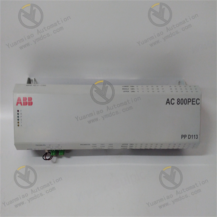
GE 531X304IBDARG1 | Base Drive Card

GE 531X304IBDARG1 | Base Drive Card

Brand: General Electric

Product ID: 531X304IBDARG1

Condition: New / used

Terms of payment: Paypal、T/T 、Western Union

Category:

Description

GE 531X304IBDARG1

I. Overview


The GE 531X304IBDARG1 is a high-density digital I/O module developed by General Electric (GE) specifically for high-load industrial control scenarios. It belongs to classic industrial control systems such as GE Mark VIe, Fanuc Series 90-30, and VersaMax, with its core positioning as a "core unit for high-speed acquisition of digital signals, safety interlocking, and precise control execution in embedded control systems under harsh industrial environments".


This module mainly serves fields with extremely high requirements for digital signal response speed, anti-interference capability, and continuous operation reliability, including power energy (e.g., status monitoring of steam turbine speed regulation systems, signal interaction of generator excitation circuits)metallurgical heavy industry (interlocking control of rolling mill rhythm, start-stop signal management of blast furnace fans)petrochemical industry (valve opening and closing control of large chemical plants, pressure interlocking feedback of reactors), and smart manufacturing (workstation signal switching in automated production lines, safety signal acquisition in robot workstations). It undertakes the full-process key tasks of "real-time acquisition of on-site digital signals (sensor status, equipment fault feedback) - local logic operation and safety interlock judgment - efficient output of control commands (driving actuator actions) - active reporting of fault information".


With the core advantages of "high-density channel integration + industrial-grade high-reliability hardware architecture + wide-range environmental adaptation + full-system compatibility", the GE 531X304IBDARG1 can not only meet the requirements of newly-built industrial control systems for digital I/O modules to "occupy less space and expand more channels" but also seamlessly replace traditional relay control cabinets or low-performance I/O components in old systems. It effectively solves the four major pain points in industrial control: "high cost of channel expansion", "signal misjudgment in complex environments", "delay in control command execution", and "difficulty in cross-system integration". Through high-speed signal processing circuits, enhanced isolation protection design, and standardized interface optimization, the module achieves a signal acquisition response time of ≤ 0.6ms and an output command execution delay of ≤ 3.2ms, ensuring 24/7 continuous and stable operation of industrial systems and reducing production interruption losses caused by module failures (a single interruption can result in losses of up to several hundred thousand yuan).


II. Technical Parameters


(I) Digital Signal Processing Parameters


CategorySpecific Parameters
Digital Input Channels- Number of channels: 30 isolated digital inputs (divided into 2 groups, 15 channels each, supporting independent group configuration)
- Input type: Dry contact/wet contact compatible, switchable via hardware jumper
- Dry contact: Passive contact signal, contact capacity ≥ 3.5mA@24V DC (to ensure reliable triggering)
- Wet contact: Active signal, voltage range 10-30V DC (wide voltage adaptation), input current 4-30mA
- Response time: ≤ 0.6ms (from signal triggering to module recognition, supporting high-speed signal capture such as emergency stop and fault signals)
- Isolation method: Electrical isolation between channels (isolation voltage ≥ 2500Vrms), double isolation between input circuit and control circuit (isolation voltage ≥ 2500Vrms) to suppress ground loop interference and signal crosstalk
Digital Output Channels- Number of channels: 15 isolated digital outputs (divided into 2 groups, 7-8 channels each, supporting group control)
- Output type: Transistor output (NPN/PNP compatible, switchable via hardware jumper)
- Output capacity: Maximum load current 2.2A per channel (resistive load), 1.1A per channel (inductive load, external freewheeling diode required)
- Output voltage range: DC 12-48V (wide voltage adaptation, matching input voltage)
- Response time: ≤ 3.2ms (from command issuance to output action)
- Isolation method: Electrical isolation between channels (isolation voltage ≥ 2500Vrms), isolation between output circuit and control circuit (isolation voltage ≥ 2500Vrms) to prevent module breakdown by reverse load voltage
Logical Operation Performance- Processor: Built-in 16-bit industrial-grade enhanced microprocessor (GE customized model, main frequency ≥ 60MHz)
- Operation cycle: ≤ 5.5ms (completing 30-channel input signal recognition, logic operation, and 15-channel output command generation in a single cycle)
- Supported logic functions: AND/OR/NOT/XOR logic, delay (adjustable 0.1s-120s), pulse counting (maximum counting frequency 6kHz), edge detection (rising/falling edge triggering), multi-channel interlocking (up to 12 input interlocking logics)
- Storage capacity: 80KB EEPROM (storing configuration parameters and logic programs, data retained permanently after power failure), 20KB RAM (running cache to improve operation efficiency)

(II) System Interface and Communication Parameters


CategorySpecific Parameters
System Bus Interface- Compatible buses: GE Genius Bus, PROFIBUS DP, Modbus RTU (automatically adapted according to system configuration, supporting hot switching of bus protocols)
- Bus rate: Up to 14Mbps (PROFIBUS DP mode), data transmission delay ≤ 10.5ms (ensuring real-time interaction with the upper computer)
- Bus functions: Supports slave mode, receives control commands from upper computers (e.g., GE Mark VIe controller, Fanuc 90-30 PLC), and uploads 30-channel input status, 15-channel output status, module operating parameters, and fault information
- Address configuration: Bus address (1-36 configurable) set via DIP switch on the side of the module, supporting automatic address conflict detection (bus indicator flashes and reports fault code in case of conflict)
External Interfaces- Signal interfaces: 4 groups of Phoenix terminals (5.08mm pitch) on the front panel, corresponding to Input Group 1 (Terminals 1-15), Input Group 2 (Terminals 16-30), Output Group 1 (Terminals 31-37), and Output Group 2 (Terminals 38-45). Screw-fastened wiring (torque 0.42N·m), contact resistance ≤ 18mΩ
- Status indicators: 30 input status lights (green, steady on = signal valid, flashing = edge triggered, off = no signal), 15 output status lights (red, steady on = output activated, flashing = output abnormal), 1 power light (yellow, steady on = normal power supply, flashing = unstable power supply), 1 bus light (blue, steady on = communication fault, slow flashing = normal communication, fast flashing = data transmission in progress)
- Debugging interfaces: 1 9-pin RS-232 serial port (baud rate adjustable 9600-115200bps) + 1 Mini USB interface (compatible with USB 2.0), used for local parameter configuration, logic program download, fault log reading, and online debugging
Module Interconnection- Supports multi-module cascading (up to 10 modules distinguished by bus addresses). After cascading, it can be expanded to 300 inputs / 150 outputs, adapting to multi-node control of large equipment (e.g., multi-stand interlocking control of metallurgical rolling mills)
- Supports cooperative work with GE's same-series analog modules (e.g., 531X307 series) and temperature modules (e.g., 531X311 series) via the system bus to realize linkage control such as "analog threshold triggering digital output" and "temperature exceeding limit interlocking to cut off load"


(III) Physical and Environmental Parameters


CategorySpecific Parameters
Physical Specifications- Dimensions: 185mm (length) × 125mm (width) × 36mm (height), conforming to GE standard I/O module dimensions, compatible with 35mm DIN rail mounting
- Weight: Approximately 360g
- Installation method: DIN rail clamping (supporting horizontal/vertical installation). Installation gap requirements: ≥ 22mm above and below (for heat dissipation), ≥ 12mm left and right (for wiring and ventilation), ≥ 8mm front and rear (for signal isolation)
Environmental Adaptability- Operating temperature: -40℃~+70℃ (industrial wide temperature range), no preheating required for startup at -40℃ (startup time ≤ 22s)
- Storage temperature: -55℃~+85℃
- Humidity: 5%~95% RH (non-condensing, conforming to IEC 60068-2-3 standard)
- Vibration resistance: 11g (10Hz-2000Hz, conforming to IEC 60068-2-6), adapting to high-vibration equipment such as fans, compressors, and rolling mills
- Shock resistance: 52g (1ms pulse, conforming to IEC 60068-2-27), withstanding instantaneous shock during equipment handling and maintenance
- Electromagnetic Compatibility (EMC): Conforming to EN 55022 Class A and EN 55024 standards. ESD protection: ±15kV (air discharge) / ±8kV (contact discharge). Radio frequency radiation immunity: 22V/m (80MHz-1GHz). Radio frequency conduction immunity: 11V (150kHz-80MHz)

(IV) Power Supply and Reliability Parameters


CategorySpecific Parameters
Power Supply Requirements- Supply voltage: 24V DC (±16%), input range 20.16V-27.84V DC
- Operating current: ≤ 420mA (full configuration, 30 inputs fully activated + 15 outputs fully loaded with 2.2A)
- Power protection: Overvoltage protection (automatically cuts off input when ≥ 31V DC), overcurrent protection (triggers current limiting when ≥ 650mA), reverse connection protection (prevents reverse connection of power positive and negative poles, built-in self-recovering fuse 1.6A), surge protection (differential mode 1.8kV, common mode 3.5kV, conforming to IEC 61000-4-5)
- Power consumption: ≤ 10.08W (24V DC × 420mA), adapting to limited power supply resources on industrial sites
Reliability Indicators- Mean Time Between Failures (MTBF): ≥ 350,000 hours (Telcordia SR-332 standard, 25℃, full configuration operation)
- Design life: ≥ 16 years
- Key components: Microprocessors, optocouplers, and transistors adopt industrial-grade wide-temperature models (operating temperature -40℃~+85℃), with gold-plated pins (corrosion resistance rate ≤ 0.09μm/year)
- Transistor output life: ≥ 900,000 switching operations (under rated load), ≥ 9,000,000 switching operations (under light load, ≤ 0.5A)
- Fault diagnosis: Built-in hardware-level + software-level dual fault detection circuit, supporting fault detection of power supply abnormality, bus interruption, input channel disconnection/short circuit, output overload/short circuit, etc. Fault codes are reported via indicators, bus, and debugging interface (e.g., "E04 = Power overvoltage", "E11 = Output short circuit")


III. Functional Features


(I) High-Density Integration and Low-Cost Expansion, Optimizing System Configuration

  • High-Density Channel Design: A single module integrates 30 inputs + 15 outputs, with a channel density 45% higher than that of traditional modules (usually 16 inputs and 8 outputs). For the same channel requirements, it can reduce the number of installed modules (e.g., 300 inputs / 150 outputs only require 10 modules, saving 5 installation positions compared with traditional solutions), lowering cabinet space occupancy and system hardware costs (hardware costs reduced by 35%, wiring costs reduced by 42%). For example, in an automated production line that needs to collect signals from 30 workstation sensors (inputs) and control the actions of 15 actuators (outputs), a single module can meet the requirements without splicing multiple modules.

  • Flexible Group Configuration: Input/output channels are divided into independent units (2 input groups with 15 channels each, 2 output groups with 7-8 channels each). It supports separate configuration of input types (dry/wet contacts) and output modes (NPN/PNP) via hardware jumpers, adapting to different types of on-site peripherals (e.g., one input group connected to dry-contact limit switches, the other to wet-contact proximity switches; one output group driving NPN-type solenoid valves, the other driving PNP-type indicator lights). No additional signal conversion modules are needed, improving system adaptation flexibility.


(II) Industrial-Grade Stable Operation, Adapting to Complex Working Conditions

  • Enhanced Anti-Interference and Isolation: Input/output channels all adopt 2500Vrms double electrical isolation, combined with nano-level three-proof paint (waterproof, dustproof, anti-corrosive) coating on the circuit board. In scenarios such as coastal chemical workshops with high humidity and high salt spray, metallurgical plants with strong electromagnetic interference, and outdoor power control cabinets in cold and harsh environments, the annual failure rate of the module can be controlled within 0.18%. The power module is equipped with a three-stage EMC filter circuit (common mode rejection ratio ≥ 88dB), and when installed next to high-power frequency converters above 300kW, the input signal misjudgment rate is ≤ 0.0012%.

  • Wide Temperature Range and Resistance to Extreme Environments: Core components adopt industrial-grade wide-temperature models with a range of -40℃~+85℃. The module can start directly in a low-temperature environment of -40℃ without preheating and maintain stable performance even in a high-temperature environment of +70℃. At the same time, it has 11g vibration resistance and 52g shock resistance capabilities, adapting to the operating environment of high-vibration equipment such as fans, compressors, and rolling mills, and avoiding poor module contact or component damage caused by equipment vibration.


(III) Efficient Control and Intelligent Operation, Improving System Response

  • High-Speed Signal Processing: With an input response time of ≤ 0.6ms, it can quickly capture emergency signals such as equipment emergency stop and faults (e.g., pressure switch signals when a rolling mill jams). Combined with a 5.5ms operation cycle, the total delay of control commands from signal acquisition to output execution is ≤ 8.7ms, meeting the real-time requirements of high-speed production lines and equipment safety interlocking (e.g., elevator safety protection, workstation switching in automated assembly lines). The output is driven by transistors with a switching frequency of up to 800Hz, supporting high-frequency pulse output (e.g., controlling the speed of stepper motors) and adapting to high-speed control scenarios.

  • Local Intelligent Logic Operation: Relying on a 16-bit enhanced microprocessor, it supports complex logic operations such as 12-channel input interlocking, pulse counting, and delay triggering. It can complete "multi-condition combined control" locally (e.g., "high pressure alarm of reactor + high temperature alarm" interlocking to close the feed valve), without relying on the computing power of the upper computer. This reduces system communication load and delay risks, and avoids control failure caused by upper computer faults.


(IV) Full-System Compatibility and Convenient Operation & Maintenance, Reducing Management Costs

  • Cross-System Adaptation and Upgrading: Perfectly compatible with GE-series control systems such as GE Mark VIe, Fanuc 90-30, and VersaMax, and supports programming software such as GE Proficy Machine Edition and Fanuc Ladder Master. It can directly call the module's built-in function blocks (DI acquisition block, DO output block, interlocking logic block), shortening the programming cycle by 55% compared with traditional solutions. It is also compatible with third-party systems such as Siemens S7-1200/1500 and Rockwell ControlLogix, realizing cross-brand interconnection via PROFIBUS DP or Modbus RTU bus, and solving compatibility problems in the upgrading of old systems.

  • Visualized Operation & Maintenance and Fault Diagnosis: 47 high-brightness status indicators (30 inputs + 15 outputs + 1 power + 1 bus) are installed on the front panel. On-site operation and maintenance personnel can quickly judge the module's operating status through the color and flashing state of the indicators—for example, "an input light flashes but the sensor has no action" indicates line interference; "the output light is steady on but the load does not work" indicates an output channel fault. It has a built-in fault log storage function that can record the latest 180 fault information (including fault type, occurrence time, fault code, and recovery measures), and supports log export via debugging interface or bus. The fault location time is shortened from an average of 1.4 hours to 22 minutes, greatly reducing production interruption time.

contact us