Description
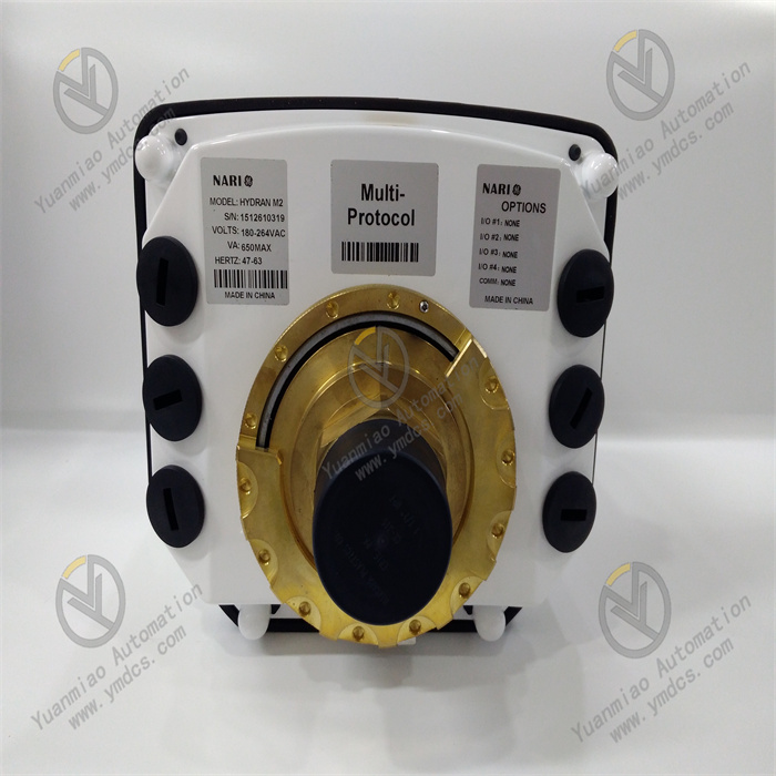
GE HYDRAN M2
I. Overview
The GE HYDRAN M2 is a compact online condition monitoring device for transformers. Its core positioning is to provide a full-lifecycle condition management solution of "real-time monitoring - fault early warning - health diagnosis" for oil-immersed power equipment. As a key technical equipment for power asset management, its essence lies in continuously capturing changes in fault gas and micro-moisture content in transformer insulating oil through high-precision sensing technology and intelligent algorithms. By combining equipment operating parameters to build a health profile, it can identify potential faults such as insulation aging and partial discharge in advance, shifting from passive emergency repair to active operation and maintenance.
II. Technical Principles and Parameters
(I) Monitoring Principles and Technical Paths
Fault Gas Monitoring
- A vacuum-resistant gas extraction membrane is used to achieve efficient separation of gases dissolved in oil from insulating oil.
- A composite gas sensor performs selective detection of hydrogen (H₂), carbon monoxide (CO), acetylene (C₂H₂), and ethylene (C₂H₄). The response sensitivity to H₂ reaches 100%, and the relative sensitivities to CO, C₂H₂, and C₂H₄ are maintained at approximately 15%, 8%, and 1.5% respectively.
- An optional pure hydrogen sensor is also available to meet different fault diagnosis accuracy requirements. The response time for 90% step change is only 10 minutes, ensuring rapid capture of fault signals.
Micro-Moisture Content Monitoring
Intelligent Diagnosis Model
(II) Performance Parameters
| Monitoring Category | Specific Parameter | Technical Index |
|---|---|---|
| Fault Gas | Measurement Range | 0-2000ppm (equivalent hydrogen) |
| Measurement Accuracy | ±10% of reading ±25ppm | |
| Repeatability | Better than ±5% or ±5ppm | |
| Micro-Moisture Content | Measurement Range | 0-100% RH (Relative Humidity) |
| Measurement Accuracy | ±2% RH | |
| Repeatability | ±2% RH | |
| Environmental Adaptability | Operating Temperature | At valve: -50°C to +90°C (high-temperature adaptation up to +120°C); Ambient: -50°C to +55°C |
| Operating Pressure | 0-700kPa (0-100psi), supporting non-vacuum working conditions | |
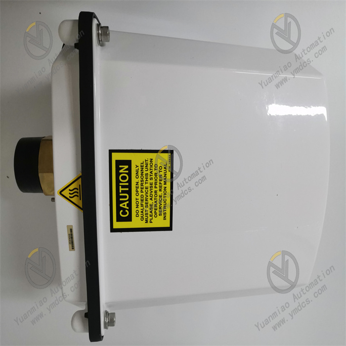
| Protection Level | NEMA 4X (IP66) cast aluminum housing, dustproof and splashproof | |
| System Characteristics | Power Requirement | 100-240VAC ±10%, 47-63Hz, maximum 650VA |
| Data Storage | 1 year of data and event logs | |
| Response Time | Sensor step response (90%) ≤10 minutes |
(III) Communication and Expansion Parameters
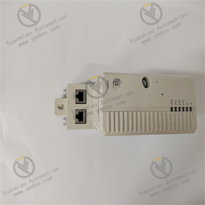
Communication Interface Configuration
- It comes standard with an isolated RS-485 serial interface. Optional TCP/IP copper or fiber optic Ethernet modules and analog modems are available.
- It supports mainstream industrial communication protocols such as DNP3, enabling seamless integration into SCADA or DCS systems for remote data transmission and centralized management.
- It is also compatible with the GE Perception software platform, supporting multi-client access and health data trend analysis.
Expansion Capability
- It provides 4 I/O expansion slots that can be adapted to isolated 4-20mA analog input/output cards, dual-channel digital input cards, etc., enabling integrated monitoring of parameters such as oil temperature and load.
- The communication expansion slot supports Ethernet module upgrades to meet the monitoring dimension expansion needs of different scenarios.
III. Core Functional Features
(I) Precise Monitoring and Early Warning to Block Fault Evolution
- A sudden change in H₂ concentration can warn of partial discharge;
- The presence of C₂H₂ indicates arc discharge;
- Increases in CO and micro-moisture reflect insulation paper aging.
(II) Intelligent Modeling and In-Depth Diagnosis to Quantify Health Status
- The winding hot-spot temperature model calculates the maximum winding temperature under load in real time, preventing accelerated insulation aging due to overheating;
- The insulation aging model quantifies the remaining insulation life through cumulative thermal effects;
- The cooling efficiency model promptly detects insufficient heat dissipation caused by cooling system faults.
(III) Minimalist Deployment and Low-Maintenance Operation to Adapt to Multi-Scenario Needs
- Installation: It adopts a "single-valve integration" design, requiring no modification to the transformer oil circuit and no power outage for deployment. It can be put into use simply by connecting the power supply and communication cables, with the installation time for a single device not exceeding 2 hours.
- Maintenance: With no moving parts, no pump structure, and a sensor service life of several years, on-site regular calibration is unnecessary. Maintenance personnel only need to remotely check the device’s self-inspection status via software, significantly reducing maintenance costs.
- Hazardous Environment Adaptation: An explosion-proof version (M2-X-HZ) certified by UL is also available, suitable for installation in Class I, Division 2 hazardous areas.
(IV) Flexible Integration and Data Connectivity to Support Asset Management Systems
- On-site data can be uploaded in real time to GE APM (Asset Performance Management) software, supporting fleet-level equipment health status comparison and analysis;
- The integrated local digital display and keypad facilitate on-site viewing of real-time data and alarm information by maintenance personnel;
- 4 programmable relays can directly link to on-site audible and visual alarm devices or emergency shutdown circuits, forming a monitoring-control closed loop. In the transformer cluster management of a power grid company, this system has enabled centralized monitoring of over 200 devices, increasing the fault diagnosis accuracy to 92%.
IV. Application Scenarios
(I) Power Transmission Network: Condition Management of Hub Transformers
- Multi-Parameter Coordinated Monitoring: It simultaneously tracks fault gases such as H₂ and C₂H₂, as well as micro-moisture content. Combined with load current, it calculates the winding hot-spot temperature to fully grasp the equipment’s insulation and thermal status.
- Remote Centralized Management: It connects to the power grid SCADA system via TCP/IP fiber optic network, allowing the dispatch center to view real-time health data of transformers across the entire network. When the H₂ concentration of a hub transformer rises by 300ppm within 24 hours, a maintenance work order is immediately triggered.
- Fault Traceability Analysis: The system stores 1 year of historical data, which can be used to trace the fault development process. For example, after a transformer tripped, the gas concentration trend chart confirmed that the fault originated from partial discharge 3 weeks earlier, providing key evidence for accident analysis.
(II) Industrial Sector: Safety Assurance for Special Transformers
- Extreme Working Condition Adaptation: The IP66 protection housing and wide temperature design (-50°C to +90°C) enable it to withstand dust, vibration, and temperature fluctuations in industrial sites.
- Rapid Fault Response: For insulation damage caused by frequent overloading of arc furnace transformers, it provides early warning through CO and micro-moisture monitoring, avoiding production interruptions due to insulation breakdown.
- Explosion-Proof Safety Upgrade: In hazardous areas such as chemical parks, the M2-X-HZ explosion-proof version is used to ensure the safe operation of monitoring equipment in flammable and explosive environments.
(III) Power Distribution System: Operation and Maintenance Optimization of Distribution Transformers
- Low-Cost Large-Scale Deployment: The single-valve installation and low-maintenance features adapt to the characteristics of a large number and wide distribution of distribution transformers, significantly reducing deployment and maintenance costs.
- Load-Matching Monitoring: By expanding load sensors and combining with the insulation aging model, it provides a basis for adjusting the load of distribution transformers, preventing accelerated insulation aging due to overloading.
- Active Maintenance Instead of Emergency Repair: A power distribution network used this system to detect micro-moisture exceeding standards in 12 transformers in advance, and replaced the seals before the rainy season, avoiding the concentrated occurrence of insulation faults after rain.
(IV) New Energy Sector: Health Monitoring of Converter Station Equipment
- Ester Oil Compatibility: It supports the monitoring of natural ester and synthetic ester insulating oils, meeting the needs of environmentally friendly insulating media for new energy equipment.
- High-Frequency Fluctuation Monitoring: In response to the rapid load changes of converter transformers, the sensor with a 10-minute rapid response can capture instantaneous fault signals.
- Linkage with Converter Control Systems: Through a 4-20mA analog output card, insulation status signals are connected to the converter control system. When gas concentration exceeds the standard, the load is automatically reduced to achieve active protection.
V. Installation and Operation & Maintenance Guidelines
(I) Installation Specifications
Mechanical Installation
- Select a sampling valve on the top or side of the transformer oil tank. Ensure the installation location is convenient for wiring and far from heat sources and vibration sources. If the temperature at the valve exceeds 90°C, a high-temperature adapter must be installed.
- Use a dedicated mounting flange to connect to the valve, with the tightening torque controlled at 15-20N·m to ensure reliable sealing without leakage. After installation, the housing grounding resistance should be ≤4Ω.
- For the explosion-proof version, strictly follow the installation requirements for Class I, Division 2 areas: maintain a safe distance from ignition sources and use explosion-proof sealed joints for cables.
Electrical Wiring
- Use copper-core cables (cross-sectional area ≥1.5mm²) for power cables, connect to a 100-240VAC power supply, and configure an independent air switch (rated current ≥5A). Strictly distinguish between the neutral wire and the live wire.
- Use shielded twisted-pair cables (for RS-485) or optical fibers (for TCP/IP) for communication cables. Ground the shield layer at one end, and maintain a distance of ≥30cm when laying parallel to power cables to avoid electromagnetic interference.
- Wire the extended I/O cables according to the module type. The 4-20mA analog signal cables must be individually shielded to ensure measurement accuracy is not affected.
(II) Parameter Configuration and Commissioning
Basic Parameter Configuration
- Access the configuration interface via the local keypad or GE-specific software to set the early warning/alarm thresholds for gas and micro-moisture. For example, set the H₂ early warning value to 150ppm and the alarm value to 300ppm.
- Configure communication parameters (address, baud rate, protocol type) to ensure normal communication with the SCADA/DCS system. For the DNP3 protocol, match the master station parameters.
- Enter the transformer nameplate parameters (rated capacity, voltage level, insulation level, etc.) to provide basic data for mathematical model calculations.
Commissioning Process
- Power-On Self-Test: After power is turned on, the system automatically performs a self-test of the sensors and communication circuits. The indicator light remains on if the self-test passes, and flashes to alarm if a fault occurs.
- Zero Calibration: In the initial stage of equipment operation, use fresh insulating oil for zero calibration to ensure accurate initial readings.
- Linkage Test: Simulate a gas concentration over-limit signal to check whether the local alarm, remote upload, and relay linkage functions work normally. The response time should be ≤1 second.
(III) Fault Troubleshooting and Maintenance
| Fault Phenomenon | Possible Causes | Solutions |
|---|---|---|
| No Data Output | 1. Power not connected or air switch tripped; 2. Incorrect communication parameter configuration; 3. Sensor fault | 1. Check the power circuit and reset the air switch; 2. Reconfigure the communication address and protocol; 3. Replace the sensor module |
| Excessive Reading Drift | 1. Contaminated or aged permeable membrane; 2. Severe ambient temperature changes; 3. Loss of calibration data | 1. Clean or replace the permeable membrane; 2. Re-read after the temperature stabilizes; install a heat preservation cover if necessary; 3. Re-perform zero calibration |
| False Alarm Trigger | 1. Alarm threshold set too low; 2. Short-term fluctuation of gas in oil; 3. Sensor interference | 1. Adjust the alarm threshold based on historical data; 2. Enable the trend alarm mode to eliminate the impact of instantaneous fluctuations; 3. Check the shielding and grounding of communication cables |
| Communication Interruption | 1. Broken or poorly connected communication cable; 2. Communication module fault; 3. Mismatched master station parameters | 1. Check cable connectivity and re-plug the connector; 2. Replace the communication module and reconfigure; 3. Verify the communication parameters between the master station and the device |