Description
GE IS215ACLEH1AB
I. Overview
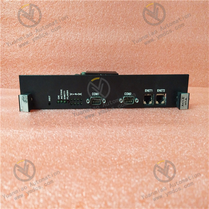
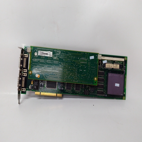
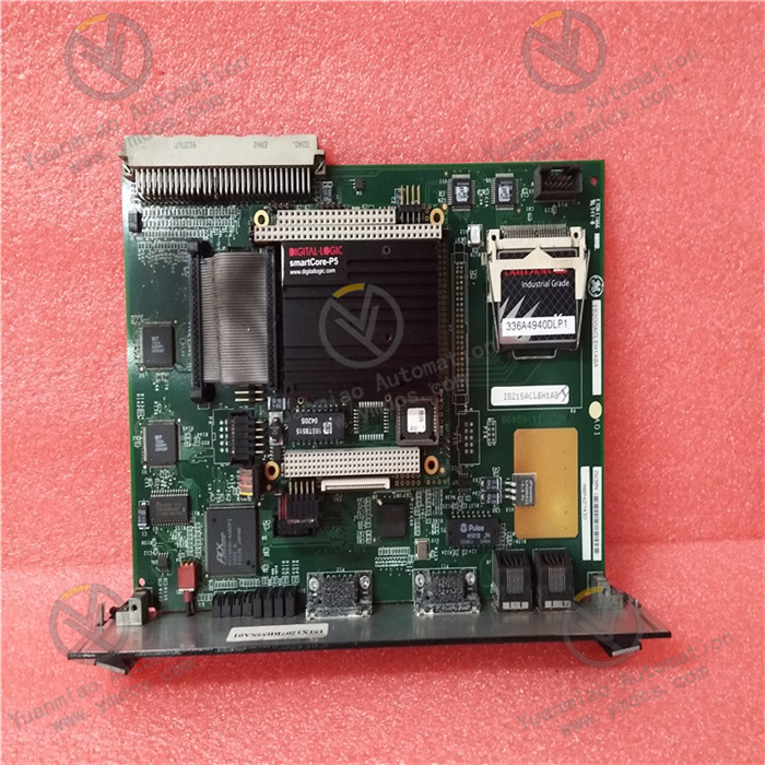
GE IS215ACLEH1AB is an Application Control Layer (ACL) module of the EX2100 series. As a microprocessor-based main controller, it is core-positioned as a central unit for "command execution - data processing - multi-network collaboration" in industrial control systems. It is deeply integrated into the GE EX2100 control system and can realize centralized control and status monitoring of equipment such as drives and exciters in scenarios including power generation, oil and gas, and water treatment through networks like Ethernet and ISBus. It serves as a key hub connecting underlying sensors/actuators and upper-level monitoring systems.
Compared with ordinary control modules, this product has three core advantages: "dual-architecture compatibility", "multi-protocol integration", and "high environmental resistance":
- It can be deployed not only in standard Inovance series drive racks but also embedded in EX2100 exciter board racks, adapting to both drive control and exciter system scenarios;
- It integrates multiple interfaces such as Ethernet and serial ports to support cross-network data interaction;
- It adopts a conformal coated PCB and anti-interference design, enabling stable operation in a wide temperature range of -30°C to 65°C and adapting to harsh working conditions at industrial sites.
II. Technical Parameters
1. Basic Specifications
| Item | Parameter Details |
|---|---|
| Equipment Type | Application Control Layer (ACL) Module, Main Controller Module |
| Compatible Systems | GE EX2100 Control System, Inovance Series Drives, EX2100 Exciter System |
| Installation Method | Standard rack mounting (occupying 2.5 slots) |
| Deployment Location | Inside industrial control cabinets, compatible with Control Assembly Backplane (CABP) and Exciter Backplane (EBKP) |
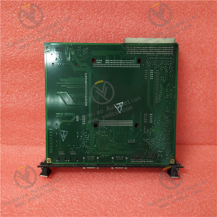
| PCB Protection | Conformal coating (moisture-proof, anti-corrosion, dust-proof) |
| Operating Temperature Range | -30°C to 65°C |
| Power Supply Requirement | 5V DC, rated current 3.0A |
2. Hardware Parameters
Processor and Storage Architecture
- CPU Configuration: 266MHz microprocessor running QNX4 operating system, with multi-task parallel processing capability;
- Cache and Memory: 128KB Level 2 cache (accelerating instruction/data access), 8MB DRAM (temporary data storage);
- Firmware Storage: 4MB flash BIOS (including system initialization program and configuration parameters, supporting firmware upgrade).
Interface and Communication Characteristics
| Interface Type | Specification Parameters | Function Purpose |
|---|---|---|
| Main Connector | P1 connector, 4-row 128-pin configuration | Connecting to backplane bus (CABP/EBKP) for power and data interaction |
| Ethernet Interface | ENET 1/ENET 2 dual ports | Supporting Ethernet communication for remote monitoring, configuration, and data transmission |
| Serial Ports | COM1/COM2 dual asynchronous serial ports | Connecting to external devices (e.g., debugging terminals, sensors) and supporting serial protocols |
| Expansion Interfaces | P3 compact flash interface, P6 reset interface, etc. | Maintenance operations such as storage expansion and system reset |
| Bus Interface | Bus target interface | Synchronizing data with other devices in the system and coordinating control logic |
3. Environmental Performance and Reliability
- Anti-interference Design: Adopting electromagnetic shielding and signal filtering technology to adapt to strong electromagnetic environments in industrial settings;
- Mechanical Resistance: Compatible with vibrating environments of rack mounting, meeting mechanical stability standards for industrial equipment;
- Service Life Indicator: Using high-quality electronic components, with Mean Time Between Failures (MTBF) meeting industrial-grade high-reliability standards.
III. Functional Features
1. Core Control Capability for Multiple Scenarios
- Dual-Architecture Adaptation: Can be deployed in two core scenarios — ① Inovance series drive racks (controlling drive equipment via CABP backplane); ② EX2100 exciter EBKP backplane (centralized management and control of exciter systems). No additional adaptation modules are required to switch application scenarios;
- Digital Signal Processing: Equipped with digital input expansion function, capable of collecting digital signals such as switch status and sensor signals, and supporting channel expansion and signal conversion;
- Logic Programming and Configuration: Supporting custom control logic, enabling functions such as independent input/output scaling and fault alarm configuration through programming.
2. Intelligent Configuration and Protection Mechanism
- Flexible Parameter Configuration:
- Input Side: Configurable filtering time (up to 1024ms), alarm mode (normal/alert-only status), and high/low alarm limits;
- Output Side: Configurable power-on default values and status during communication interruption (maintaining last value/restoring default value);
- Comprehensive Fault Monitoring: Featuring functions such as input open-circuit detection (current mode), under-range/over-range detection (input/output), and communication fault diagnosis, capable of proactively reporting fault status;
- Safety Control Logic: Supporting fault isolation mechanism, where a single channel fault does not affect the overall system operation, ensuring control continuity.
3. Efficient Communication and Collaboration
- Multi-Network Integration: Realizing data interaction with upper-level monitoring systems (e.g., SCADA) via Ethernet, and linking with underlying equipment through ISBus/backplane bus, forming a "monitoring - control - execution" closed loop;
- Remote O&M Support: Enabling remote access to the module via Ethernet interface for program downloading, parameter modification, and status monitoring, reducing on-site O&M costs;
- Serial Expansion Compatibility: COM1/COM2 ports supporting multiple asynchronous serial protocols, allowing connection to peripheral devices such as printers and barcode scanners to expand the system's functional boundaries.
4. High-Reliability Design
- Hardware Protection: Conformal coated PCB can resist moisture, dust, and chemical corrosion at industrial sites, extending the module's service life;
- Startup Guarantee: Flash BIOS provides a reliable system initialization process, ensuring stable startup of the module after power-on and avoiding faults caused by configuration loss;
- Maintenance Convenience: Rapid system recovery and upgrade can be completed through the reset interface and flash interface, reducing fault handling time.
IV. Operation, Maintenance and Troubleshooting
Daily Maintenance Points
- Status Monitoring: Check the module's operating parameters (CPU load, memory usage, communication status) via the Ethernet interface daily to ensure no fault alarms;
- Interface Inspection: Inspect the P1 connector and backplane wiring monthly to confirm no pin oxidation or looseness, preventing poor contact;
- Firmware Maintenance: Verify the BIOS version quarterly and upgrade the firmware according to GE technical announcements to fix known vulnerabilities;
- Environmental Control: Ensure the temperature inside the control cabinet is within the range of -30°C to 65°C, and prevent dust accumulation from affecting heat dissipation and interface performance.
Common Faults and Solutions
| Fault Phenomenon | Possible Causes | Solutions |
|---|---|---|
| Module fails to start, no indicator light | 1. Abnormal power supply (5V DC not connected or overcurrent); 2. Damaged BIOS; 3. Faulty reset circuit | 1. Use a multimeter to test the power supply voltage, confirm normal 5V DC input, and check the power fuse; 2. Re-flash the BIOS firmware via the P3 interface; 3. Inspect the P6 reset interface and replace reset circuit components if necessary |
| Ethernet communication interruption | 1. Loose network cable or faulty interface; 2. IP configuration conflict; 3. Damaged Ethernet port | 1. Re-plug the network cable and replace with a test cable to rule out cable issues; 2. Verify the module's IP address to avoid conflicts with other devices; 3. Switch to the backup ENET 2 port and replace the faulty port if communication is restored |
| No digital input signal | 1. Incorrect input channel configuration; 2. Sensor wiring issues; 3. Open-circuit detection triggered | 1. Reconfigure the input filtering time and alarm mode to ensure parameter matching; 2. Check the wiring between the sensor and COM port to confirm valid signals; 3. Troubleshoot for broken input lines, repair, and reset the fault status |
| Abnormal output status (deviation/no output) | 1. Incorrect output default value configuration; 2. Status locked due to communication interruption; 3. Faulty output channel | 1. Re-set the output power-on default value and communication interruption protection strategy; 2. Restore communication between the module and the upper computer, and manually reset the output status; 3. Isolate the faulty channel and switch to a backup channel via programming |
| Serial port communication failure | 1. Mismatched port parameters (baud rate/parity bit); 2. Reversed cable wiring; 3. Faulty port hardware | 1. Verify COM port parameters (e.g., baud rate 9600, no parity) to ensure consistency with peripheral devices; 2. Check the pin definition of the serial cable and correct the wiring; 3. Replace the serial port or repair the hardware interface |


