Description
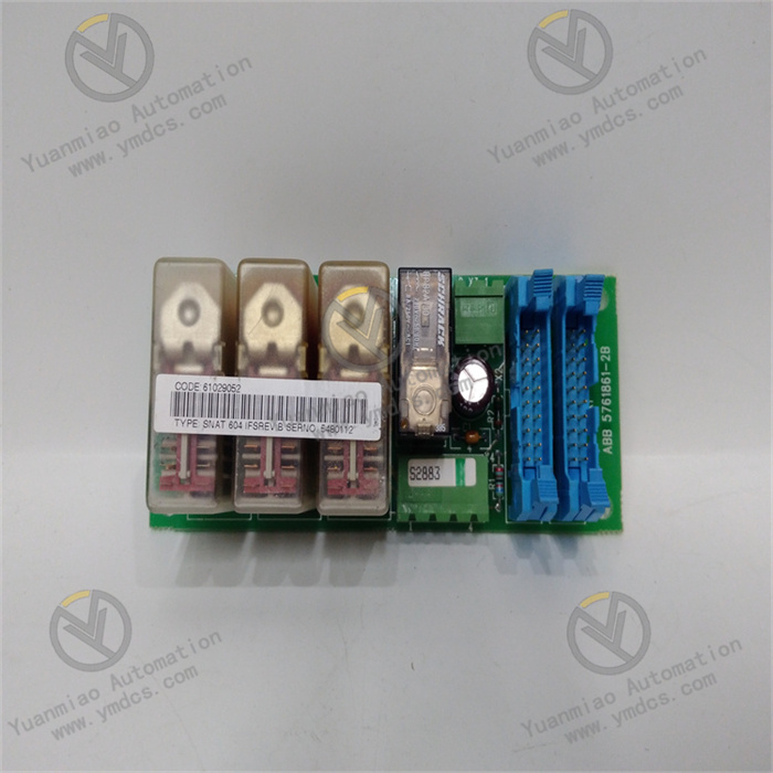
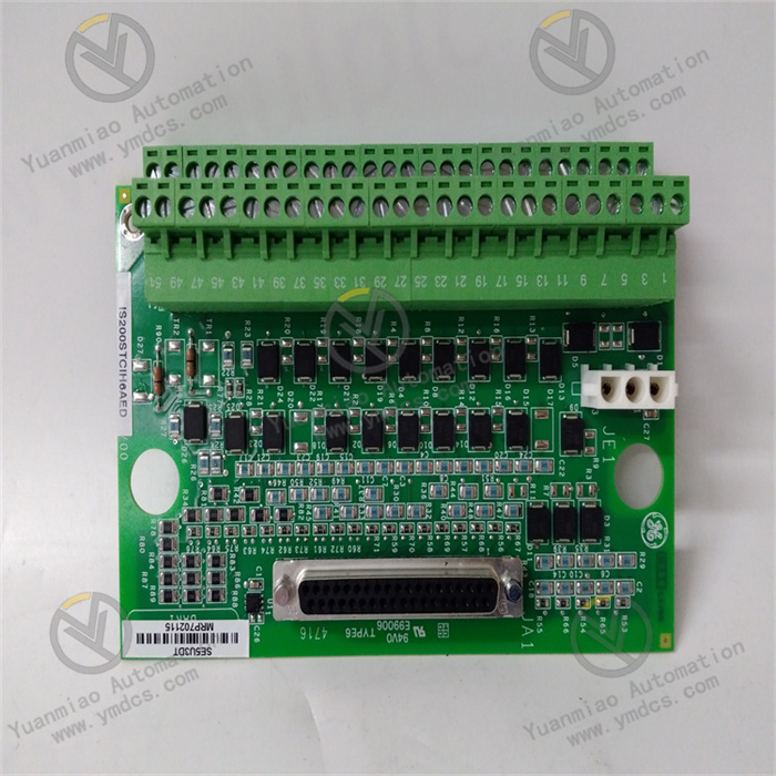
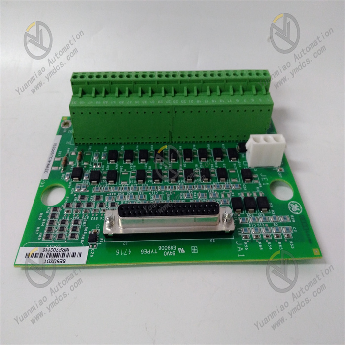
Functional Features Communication Function: It has built-in Ethernet user support for communication, and supports application protocols such as SRTP and Modbus TCP/IP, providing a real-time link for the connected system. Processing Capacity: It has scalable processing capabilities. Users can create systems that meet current needs, and in the future, more powerful systems can be created without changing the software. Motion Control: It integrates motion control functions and supports high-performance control in point-to-point applications. Fieldbus Interface: It has multiple fieldbus interfaces, supports distributed control and/or I/O. Users can select fieldbus interface modules that are easy to install and quickly configure. Programming Support: It can be programmed through Proficy Logic Developer PLC Machine Edition, and supports multiple programming languages such as Ladder Diagram (LDI), Instruction List (IL), Structured Text (ST) and C blocks. Signal Processing: As a servo terminal board, it can process various signals. It has two coil outputs, two channels and two pulse frequency inputs, and also has 8 LVDTs (Linear Variable Differential Transformers). It can be connected to digital switches or sensors to achieve control and monitoring of related devices.
Technical Parameters Operating Voltage: 24V DC. Output Frequency: 48 - 62Hz. Processing Speed: 133MHz. Ambient Temperature: 0℃ - 60℃. Ambient Humidity: 20% - 80%, without condensation.
Installation and Configuration of GE IS200STCIH6AED Installation Steps Preparation Work: Before installation, ensure that all necessary tools such as screwdrivers and wrenches are ready. At the same time, confirm that the installation environment meets the requirements of the device, such as the temperature (0℃ - 60℃), humidity (20% - 80%, without condensation) and other conditions. Check whether the appearance of the device is damaged and whether the accessories are complete. Selection of Installation Location: Select a suitable location to install the device. Usually, factors such as the convenience of connection with other devices and the heat dissipation situation need to be considered. The device is compactly designed and can be installed in a standard control cabinet. Ensure that there is enough space at the installation location for subsequent maintenance and operation. Electrical Connection: Power Connection: According to the requirements of the device, correctly connect the 24V DC power supply to the power interface of the device. Ensure that the power connection is firm to avoid problems such as looseness or short circuit. Signal Connection: According to the actual application requirements, connect the relevant input and output signal cables. For example, connect the signal cables of speed sensors, LVDT (Linear Variable Differential Transformers) and other devices to ensure that the signal connection is correct and stable. Communication Connection: If communication with other devices is required, such as through Ethernet or fieldbus, connect the corresponding communication cables. For Ethernet communication, use standard Ethernet cables to connect to network devices; for fieldbus communication, connect the communication cables according to the corresponding fieldbus protocol. Fixing the Device: Use tools such as screwdrivers to fix the device at the installation location, ensuring that the device is firmly installed to avoid problems such as looseness or vibration during operation.
Configuration Steps Software Preparation: Install Proficy Logic Developer PLC Machine Edition software, which is used for programming and configuring the device. Ensure that the software version is compatible with the device and complete the installation according to the software installation wizard. Device Identification: Connect the installed device to the computer, open the Proficy Logic Developer PLC Machine Edition software, and the software will automatically identify the device. If the device cannot be identified, check the communication connection and software settings of the device to ensure normal communication. Parameter Configuration: Communication Parameter Configuration: According to the actual application requirements, configure the communication parameters of the device, such as the IP address, subnet mask, gateway and other parameters for Ethernet communication, or the relevant parameters for fieldbus communication. Ensure that the communication parameters match the communication settings of other devices. Input and Output Parameter Configuration: Configure the input and output parameters of the device, such as setting the working mode of the coil output, the parameters of the pulse frequency input, etc. According to the characteristics of the connected sensors and actuators, correctly configure the relevant parameters to ensure that the device can accurately receive and send signals. Motion Control Parameter Configuration: If the device is used for motion control, configure the relevant motion control parameters, such as speed control, position control and other parameters. According to the actual application requirements, set appropriate motion control parameters to achieve precise control of the device. Programming Operation: Use Proficy Logic Developer PLC Machine Edition software to write programs such as Ladder Diagram (LDI), Instruction List (IL), Structured Text (ST) or C blocks according to specific control logic and application requirements. During the programming process, follow relevant programming specifications and standards to ensure the stability and reliability of the program. Program Download and Debugging: After completing the programming, download the written program to the device. Before downloading the program, ensure that the device is in the correct working mode. After the download is complete, conduct program debugging to check whether the operation status and control logic of the device are correct. If problems are found, perform fault diagnosis and debugging through the software, and modify the errors in the program to ensure the normal operation of the device.