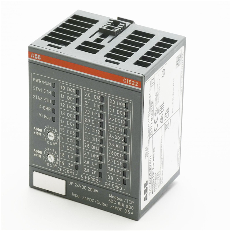
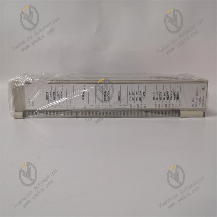
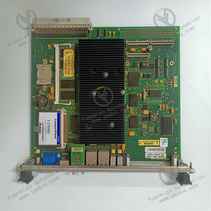
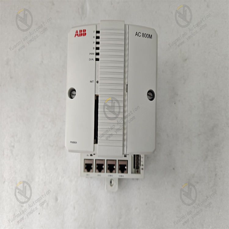
Description
GE IS200DTAIH1ACC
I. Overview
The GE IS200DTAIH1ACC is a high-density industrial-grade digital output module in the Speedtronic Mark VIe series control system, specifically designed for the execution of discrete control signals in industrial-grade steam turbines, gas turbines, and combined cycle units. As the "digital control execution terminal" of the Mark VIe system, it undertakes the core responsibilities of converting logical commands issued by the control module (such as valve start-stop, motor start-stop, alarm triggering, and interlock control) into switch signals recognizable by on-site equipment, as well as implementing signal isolation, power driving, status feedback, and fault diagnosis. It is a key hardware connecting the control layer and the on-site execution layer, ensuring the accurate implementation of control commands. It is widely used in industrial scenarios with strict requirements for digital output reliability, anti-interference capability, and environmental adaptability, such as power generation, petrochemicals, metallurgy, and energy industries.
This module adopts a standard 3U VME industrial board form factor (approximately 100mm in height, 233mm in width, and 24mm in thickness) and has no independent operation panel. It realizes high-speed data interaction and stable power supply with the control module and power module through the system backplane. The surface of the module adopts a military-grade anti-interference layout; key power devices (such as industrial-grade relays and high-voltage-resistant MOSFETs) are equipped with metal shields and high-density heat sinks. The pin soldering process complies with the IPC-A-610 Class 3 industrial standard, enabling it to withstand long-term high-load operation and complex electromagnetic environments (such as high-voltage motor start-stop and high-frequency frequency converter interference). At the same time, it has wide-temperature, moisture-proof, and salt-fog-resistant characteristics, allowing stable operation in industrial sites with high interference, wide temperature differences, and high humidity, thus ensuring the continuity of digital output signals and the safety of equipment driving.
II. Technical Specifications
1. Signal Output and Driving Specifications
| Specification Category | Specific Specifications |
|---|---|
| Output Channel Configuration | 16 independent digital output channels, supporting group switching between relay output and transistor output (8 channels per group, independently configurable) |
| Output Signal Types | Relay output: Dry contact, supporting software configuration of normally open/normally closed modes; Transistor output: Wet contact, supporting software switching of NPN/PNP polarity |
| Output Voltage Range | Relay output: Compatible with 24V DC, 48V DC, 110V AC, and 220V AC loads; Transistor output: 24V DC±10% |
| Output Current Capacity | Relay output: Maximum single-channel resistive load current 5A, inductive load current 2A (at power factor 0.7); Transistor output: Maximum single-channel continuous current 2A, peak current 6A (duration ≤ 100ms) |
| Response Time | Relay output: Pull-in time ≤ 12ms, release time ≤ 6ms; Transistor output: Turn-on/turn-off time ≤ 80μs |
| Signal Isolation | Isolation voltage between channels ≥ 2.5kVrms, isolation voltage between output and backplane ≥ 3kVrms, isolation voltage between input and output ≥ 3kVrms, effectively blocking common-mode interference and ground loops |
| Status Feedback | Each channel is equipped with a high-precision current detection resistor (accuracy ±2%), supporting output status (on/off), load current monitoring, and overload detection; feedback data update frequency ≥ 10Hz |
2. Electrical and Environmental Specifications
- Power Supply Requirements: Digital circuit power supply +5V DC (allowable fluctuation ±5%), drive circuit power supply ±12V DC (allowable fluctuation ±5%), independent relay coil power supply +24V DC (allowable fluctuation ±10%); Maximum power consumption ≤ 22W (when all channels are relay outputs at full load), adopting a hybrid heat dissipation design of "natural heat dissipation + local forced air cooling" (a micro silent fan integrated in the relay area), full-load operating temperature ≤ 58℃;
- Operating Temperature: -30℃~70℃ (wide-temperature design), suitable for extreme temperature scenarios such as outdoor control cabinets in frigid zones and high-temperature industrial workshops (e.g., steel plants, oil refineries);
- Storage Temperature: -40℃~85℃, no risk of component aging, pin corrosion, or insulation layer aging during long-term storage;
- Relative Humidity: 5%~95% (non-condensing), the board surface is coated with a moisture-proof and salt-fog-resistant coating with a thickness of ≥0.12mm (complying with MIL-STD-883H standard), enabling stable operation in coastal high-salt-fog environments (5% salt fog concentration, no corrosion after 96 hours of continuous spraying);
- Anti-Interference Performance: Complies with the IEC 61000-6-4 industrial anti-interference standard; Electrostatic Discharge (ESD) protection: ±4kV (contact discharge)/±8kV (air discharge); Electrical Fast Transient (EFT) protection: ±2kV (power port)/±1kV (signal port); Radio Frequency (RF) radiation immunity ≥ 25V/m (80-1000MHz); RF conducted immunity ≥ 10V (150kHz-80MHz);
- Surge and Overvoltage Protection: The output port is equipped with ±6kV (1.2/50μs) surge protection (complying with IEC 61000-4-5 standard) and a built-in overvoltage protection circuit (overvoltage threshold of relay output terminal: 280V AC/60V DC), preventing damage to the module caused by back electromotive force from inductive loads (motors, solenoid valves) during power-off and power grid fluctuations.
3. Physical and Interface Specifications
- Dimensions: 3U VME board form factor (100mm×233mm×24mm), compatible with standard 19-inch industrial control cabinet installation, supporting hot swapping (requires Mark VIe system authorization, complying with IEEE 1613 standard);
- Weight: Approximately 1.1kg (including relays, heat sinks, and shields);
- Output Interface: 16 Phoenix terminal interfaces (each channel corresponds to 1 output terminal + 1 common terminal + 1 feedback terminal). The terminals are made of anti-corrosion gold-plated material, supporting screw-fastened wiring. Wire specifications: 0.5-4mm² for relay output, 0.5-2.5mm² for transistor output. It has an anti-misinsertion design (terminal color distinction: red for output terminal, black for common terminal, blue for feedback terminal);
- Indicator Lights: The front panel of the board is equipped with 6 main LED indicators (PWR: Power status, green; RUN: Operation status, green; ERR: Fault status, red; COMM: Communication status, yellow; GRP1/GRP2: Channel group status, green). The GRP1/GRP2 lights being steadily on indicates that the corresponding 8 channels are normal, while blinking indicates overload/short circuit in the group. Each channel is equipped with 2 micro LED lights (OUT: Output status, on means conducting; FB: Feedback status, on means normal load response), providing intuitive feedback on the single-channel operation status.
4. Communication and Diagnostic Specifications
- Communication Interface: 1 VME64x high-speed backplane interface, with a data transmission rate of 80MB/s with the control module, supporting interrupt requests (e.g., triggering interrupts in case of output overload, short circuit, or relay sticking, with response time ≤ 50ms);
- Diagnostic Functions: Supports channel-level fault diagnosis, including load short-circuit detection (response time ≤ 80ms), overload detection (triggered when current exceeds 120% of the rated value), relay sticking detection (alarmed when output command is inconsistent with feedback status for 50ms), drive chip fault detection (MOSFET/relay coil open circuit), and power fault detection (±12V/+24V power supply abnormality). Fault information includes channel number and fault type (e.g., "GRP2 CH10 Short Circuit"), which is uploaded to the monitoring system via the backplane bus;
- Configuration Method: Supports remote configuration via GE ToolboxST software, including channel type (relay/transistor), output mode (normally open/normally closed/NPN/PNP), overload protection threshold (1.1-1.5 times the rated current), interrupt trigger conditions (overload/short circuit/sticking), and feedback detection sensitivity. Configuration parameters are saved after power-off (built-in 128KB EEPROM), supporting configuration file backup and batch deployment.
III. Functional Features
1. High-Density Multi-Type Output, Adapting to Complex Load Scenarios
- Flexible Configuration of 16 Channels: The 16 output channels are designed in groups of "8 channels per group", supporting mixed configuration of relays and transistors (e.g., GRP1 set as relay output to drive 220V AC motor contactors, GRP2 set as transistor output to drive 24V DC solenoid valves). It can meet the on-site diverse load driving needs without additional modules, reducing cabinet space occupation by 40% compared with single-type output modules. It is particularly suitable for actuator-dense scenarios such as steam turbine valve control and boiler auxiliary machine start-stop;
- Wide Load Compatibility: Relay outputs are compatible with AC/DC multi-voltage level loads (24V DC-220V AC), and the single-channel 5A high current can drive heavy-duty equipment (e.g., 3kW motor contactors, large valve actuators); Transistor outputs have 2A continuous current + 6A peak current, adapting to high-frequency action loads (e.g., high-frequency commutation of fuel solenoid valves with a response frequency ≥ 1.2kHz), meeting the driving needs of loads with different powers and action frequencies;
- Balancing High-Frequency and Heavy-Load Requirements: Transistor outputs have a turn-on/turn-off time of ≤ 80μs, enabling high-frequency control (e.g., precise adjustment of gas turbine fuel valves); Relays adopt industrial-grade sealed relays (Brand: Omron G5LE, MTBF ≥ 800,000 operations), with silver alloy-plated contacts that are resistant to arc corrosion, ensuring long-term reliable operation in heavy-load scenarios (e.g., motor contactors with 100 start-stop cycles per day can have a service life of more than 10 years).
2. Full-Link Anti-Interference and Safety Protection, Ensuring Reliable Operation
- Triple Isolation Protection: 2.5kVrms isolation between channels, 3kVrms isolation between output and backplane, and 3kVrms isolation between input and output. Combined with the independent power supply design for analog and digital circuits, it blocks common-mode interference (e.g., 1.5kV common-mode voltage generated by frequency converters) and ground loops in industrial sites, avoiding load crosstalk between different channels; The power drive circuit adopts a dual design of photoelectric isolation + magnetic isolation, preventing reverse intrusion of load interference into the control layer, with a signal transmission accuracy of 99.999%;
- Multi-Level Load Protection: Each channel is equipped with built-in overcurrent protection (self-recovering fuses for relay channels with a rated current of 6A; current-limiting resistors + overheating protection for transistor channels). When the load is short-circuited or overloaded (e.g., motor stall current exceeding 5A), the output is cut off within 80ms to avoid damage to the module and the load; The output port has ±6kV surge protection and overvoltage protection to absorb back electromotive force from inductive loads during power-off (e.g., pulses above 200V generated by motor power-off) and protect drive chips (e.g., MOSFET model IRF540N);
- Closed-Loop Control Feedback: Each channel integrates high-precision current detection and status feedback, forming a closed-loop control of "command issuance - output execution - status feedback - abnormal alarm": After the control module issues a "valve closing" command, the module output is turned on, and the load current is confirmed through the feedback signal (e.g., normal operating current of the solenoid valve is 0.8A). If there is no current in the feedback (the "OUT" light is on but the "FB" light is off), the load open circuit is immediately determined and an alarm is triggered, avoiding control misjudgment of "command issued but load not activated" and ensuring unit safety (e.g., the valve is indeed closed during emergency shutdown of the steam turbine).
3. Intelligent Diagnosis and Flexible Configuration, Reducing Operation and Maintenance Costs
- Software-Based Parameter Customization: Channel parameters can be configured remotely via GE ToolboxST software without on-site adjustment of hardware jumpers: For example, to change a channel from relay output to transistor output, you only need to modify the "channel type" in the software and apply it, which takes effect within 5 seconds; It supports custom overload thresholds (e.g., setting the threshold to 1.2A when driving a 1A solenoid valve) to adapt to different load characteristics; Configuration files can be backed up to a PC and directly imported during batch deployment of modules of the same model, improving operation and maintenance efficiency by 60%;
- Precise Fault Location: Built-in channel-level fault diagnosis, with fault information fed back through both LED indicators and the monitoring system: For example, if the GRP2 light blinks and the ERR light is on, combined with the "GRP2 CH12 Overload" prompt on the monitoring interface, maintenance personnel can directly locate the faulty channel and load without checking on-site equipment one by one; The relay sticking detection function (alarmed when the command is "open" but the feedback is "on" for 50ms) can detect relay faults in advance, avoiding load misoperation (e.g., shutdown caused by incorrect valve closing);
- Status Visualization and Remote Monitoring: The "OUT/FB" dual LED light design for each channel allows on-site maintenance personnel to judge the status without connecting software (e.g., "OUT" on and "FB" off = load open circuit; "OUT" off and "FB" on = feedback fault); The monitoring system can real-time view the output current of each channel and the number of relay operations (cumulative count with an accuracy of ±1 time), providing data support for preventive maintenance (e.g., if the number of operations of a relay reaches 600,000 times, replacement within 3 months is recommended).
4. Industrial-Grade High-Reliability Design, Adapting to Harsh Environments
- Wide-Temperature and Extreme Environment Adaptation: With a wide operating temperature range of -30℃~70℃, the relay pull-in time is still ≤ 15ms at -30℃, and the transistor output current is stable at 70℃ (chip temperature ≤ 65℃ under 2A continuous output); The moisture-proof and salt-fog-resistant coating and gold-plated terminals enable long-term operation in coastal high-humidity and high-salt-fog environments (e.g., offshore platform power stations), avoiding faults caused by component corrosion;
- Mechanical and Electrical Durability: Complies with the IEC 60068-2-6 standard for vibration protection (10-500Hz, 10g acceleration sinusoidal vibration) and the IEC 60068-2-27 standard for shock protection (100g acceleration, 6ms pulse). It can withstand vibration and shock during equipment transportation and industrial on-site operation, avoiding relay contact loosening and drive chip detachment; Key components adopt industrial-grade long-life devices, with relay operation count ≥ 800,000 times and transistor continuous operation life ≥ 150,000 hours, reducing replacement frequency;
- Optimized Heat Dissipation Design: A micro silent fan (rotation speed 3000rpm, noise ≤ 38dB) is integrated in the relay area. Combined with a U-shaped aluminum heat sink, it reduces the relay operating temperature by 20℃ (when all channels are on), avoiding contact oxidation and service life reduction caused by high temperatures; Transistor channels adopt patch-type heat dissipation pads (thermal conductivity 3.0W/m·K), with a heat dissipation area increased by 40% compared with traditional designs. The chip temperature is ≤ 65℃ under 2A continuous output, ensuring long-term stable operation.