Description
GE IS200DTAIH1ABB
I. Overview
The GE IS200DTAIH1ABB is a high-density digital output module in the Mark VIe series control system, specifically designed for discrete control signal output in industrial-grade steam turbines, gas turbines, and combined cycle units. As the "digital execution core" of the Mark VIe system, it undertakes the critical responsibilities of converting logical commands issued by the control module (such as valve start-stop, motor control, and alarm triggering) into switch signals recognizable by on-site equipment, as well as implementing signal isolation, power driving, and status feedback. It serves as the core hardware connecting the control layer and the execution layer, ensuring that on-site equipment responds accurately to control commands. It is widely used in industrial scenarios with strict requirements for digital output reliability and anti-interference capability, such as power generation, petrochemicals, and metallurgy.
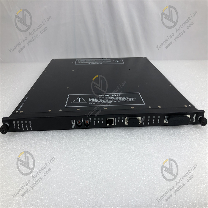
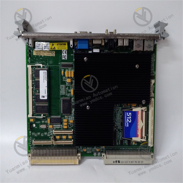
This module adopts a standard 3U VME industrial board form factor (approximately 100mm in height, 233mm in width, and 22mm in thickness) and has no independent operation panel. It realizes data interaction and power supply with control modules and power modules through the system backplane. The surface of the module features an industrial-grade anti-interference layout; key power drive chips (such as relays and MOSFETs) are equipped with metal shields and heat sinks, and the pin soldering process complies with the IPC-A-610 Class 3 industrial standard. It can withstand long-term high-load operation and complex electromagnetic environments (such as motor start-stop and high-frequency interference from frequency converters), ensuring the stability of digital output signals and the safety of equipment driving, and adapting to harsh operating conditions in industrial sites, including high interference, wide temperature differences, and high humidity.
II. Technical Specifications
1. Signal Output and Driving Specifications
| Specification Category | Specific Specifications |
|---|---|
| Output Channel Configuration | 16 independent digital output channels, supporting relay output/transistor output switching (configurable in groups of 8 channels) |
| Output Signal Types | Relay output (dry contact, configurable as normally open/normally closed); Transistor output (wet contact, NPN/PNP polarity selectable) |
| Output Voltage Range | Relay output: Supports 24V DC/48V DC/220V AC loads; Transistor output: 24V DC±10% |
| Output Current Capacity | Relay output: Maximum single-channel load current 5A (resistive load), 2A (inductive load); Transistor output: Maximum single-channel continuous current 2A, peak current 5A (≤100ms) |
| Response Time | Relay output: Pull-in time ≤ 10ms, release time ≤ 5ms; Transistor output: Turn-on/turn-off time ≤ 100μs |
| Signal Isolation | Isolation voltage between channels ≥ 2kVrms, isolation voltage between output and backplane ≥ 3kVrms, blocking common-mode interference and ground loops |
| Status Feedback | Each channel has a built-in current detection resistor, supporting output status feedback (on/off) and overload detection, with feedback accuracy of ±5% |
2. Electrical and Environmental Specifications
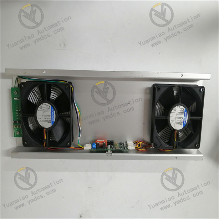
- Power Supply Requirements: Input voltages are +5V DC (for digital circuits), ±12V DC (for drive circuits), and +24V DC (for relay coil power supply), with an allowable voltage fluctuation range of ±5%; Maximum power consumption ≤ 20W (when all channels are relay outputs), adopting natural heat dissipation + local forced air cooling (a micro fan integrated in the relay area), and operating temperature ≤ 55℃;
- Operating Temperature: -25℃~65℃ (wide-temperature design), suitable for extreme scenarios such as high-temperature workshops, outdoor control cabinets, and frigid regions;
- Storage Temperature: -40℃~85℃, with no risk of component aging or pin corrosion during long-term storage;
- Relative Humidity: 5%~95% (non-condensing), the board surface is coated with a moisture-proof insulating coating (thickness ≥ 0.1mm), and it can be used in coastal high-salt-fog environments (salt fog concentration of 5%);
- Anti-Interference Performance: Complies with the IEC 61000-6-2 industrial anti-interference standard; Electrostatic Discharge (ESD) protection: ±2kV (contact discharge)/±4kV (air discharge); Electrical Fast Transient (EFT) protection: ±1kV (power port)/±0.5kV (signal port); Radio Frequency (RF) radiation immunity ≥ 10V/m (80-1000MHz);
- Surge Protection: The output port is equipped with ±5kV (1.2/50μs) surge protection to prevent damage to the module caused by back electromotive force generated when inductive loads (such as motors and solenoid valves) are powered off.
3. Physical and Interface Specifications
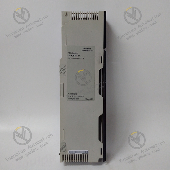
- Dimensions: 3U VME board form factor (100mm×233mm×22mm), compatible with standard 19-inch industrial control cabinet installation, supporting hot-swapping (requires Mark VIe system authorization);
- Weight: Approximately 0.9kg (including relays and heat sinks);
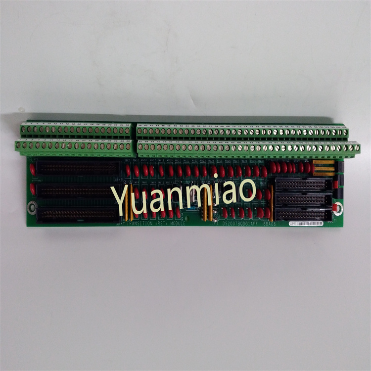
- Output Interface: 16 Phoenix terminal interfaces (each channel corresponds to 1 output terminal + 1 common terminal + 1 feedback terminal), supporting screw-fastened wiring. Wire specifications: 0.5-4mm² (for relay output)/0.5-2.5mm² (for transistor output), with anti-misinsertion design (terminals are color-coded to distinguish output/feedback);
- Indicator Lights: The front panel of the board is equipped with 6 LED indicators (PWR: Power status, green; RUN: Operation status, green; ERR: Fault status, red; COMM: Communication status, yellow; GRP1-GRP2: Channel group status, green). The GRP1-GRP2 lights being steadily on indicates that the corresponding 8 channels are normal, while blinking indicates overload/short circuit in the group. Each channel has 2 corresponding micro LED lights (located next to the terminals): the "OUT" light being on indicates the output is on, and the "FB" light being on indicates normal feedback (confirming the load has responded).
4. Communication and Diagnostic Specifications
- Communication Interface: 1 VME64x backplane interface, with a data transmission rate of 40MB/s with the control module, supporting interrupt requests (e.g., triggering an interrupt when output is overloaded);
- Diagnostic Functions: Supports channel short-circuit detection (response ≤ 100ms when load is short-circuited), overload detection (triggered when current exceeds 120% of the rated value), relay sticking detection (alarmed when output command is inconsistent with feedback status), and drive circuit fault detection. Fault information (including faulty channel number and fault type) is uploaded to the monitoring system via the backplane bus;
- Configuration Method: Supports remote configuration of channel type (relay/transistor), output polarity (NPN/PNP), overload protection threshold (1.1-1.5 times the rated current), and interrupt trigger conditions (triggered by overload/short circuit) via GE ToolboxST software. Configuration parameters are retained after power-off.
III. Functional Features
1. High-Density Multi-Type Digital Output Driving
- Flexible Output of 16 Channels: The 16 output channels adopt a "dual-group design" (8 channels per group), supporting mixed configuration of relays and transistors. It can drive different types of loads simultaneously without additional modules (e.g., relay channels drive 220V AC motor contactors, and transistor channels drive 24V DC solenoid valves), significantly saving cabinet space (reducing space occupation by 50% compared to 8-channel modules). It is particularly suitable for industrial scenarios with dense actuators (such as steam turbine valve control, boiler feed pump start-stop, and alarm light triggering);
- Wide Load Adaptation: Relay outputs are compatible with AC/DC loads (24V DC-220V AC), and the single-channel 5A high-current capacity can drive heavy-duty equipment (e.g., 3kW motor contactors); Transistor outputs have 2A continuous current and 5A peak current, adapting to high-frequency action loads (e.g., high-frequency commutation of solenoid valves with response time ≤ 100μs), meeting diverse driving needs in industrial sites;
- Rapid Response and Reliable Operation: Transistor outputs have a turn-on/turn-off time of ≤ 100μs, enabling high-frequency control (e.g., high-frequency adjustment of fuel valves with a response frequency ≥ 1kHz); Relay outputs use industrial-grade sealed relays (MTBF ≥ 500,000 operations) with short pull-in/release times, ensuring that loads respond quickly to control commands (e.g., valves close within 10ms during emergency shutdown).
2. Full-Link Anti-Interference and Safety Protection
- High-Strength Isolation Protection: 2kVrms isolation between channels and 3kVrms isolation between output and backplane block common-mode interference (such as 1kV common-mode voltage generated by frequency converters) and ground loops in industrial sites, avoiding load crosstalk between different channels; The output circuit adopts a dual design of photoelectric isolation + power isolation, and digital control signals are completely electrically isolated from power drive circuits, preventing load interference from intruding into the control layer in reverse, with a signal transmission accuracy of 99.999%;
- Load Protection Mechanism: Each channel has built-in overcurrent protection (self-recovering fuses for relay channels, current-limiting resistors for transistor channels). When the load is short-circuited or overloaded (e.g., motor stalling causes current to exceed 5A), the output is quickly cut off (≤ 100ms) to avoid damage to the module and the load; The output port has ±5kV surge protection to absorb back electromotive force generated when inductive loads (such as motors and solenoid valves) are powered off (e.g., high-voltage pulses generated by power-off of motors and solenoid valves), protecting drive chips;
- Status Closed-Loop Feedback: Each channel integrates current detection and status feedback functions. After an output command is issued, the feedback signal is used to confirm whether the load is actually turned on (e.g., the "OUT" light is on but the "FB" light is off, indicating an open load), forming a "command-output-feedback" closed-loop control. This avoids misjudgment of "command issued but load not activated" caused by load wire breakage or poor contact, ensuring reliable execution of control logic (e.g., executing the next operation only after confirming that the valve is indeed closed).
3. Flexible Configuration and Intelligent Diagnosis
- Software-Based Parameter Customization: Via GE ToolboxST software, the output type (relay/transistor), polarity (NPN/PNP), overload threshold (e.g., setting the overload threshold of transistor channels to 2.4A), and interrupt trigger conditions (e.g., triggering an emergency interrupt in case of short circuit) of each channel can be configured remotely. No on-site adjustment of hardware jumpers is required, adapting to scenarios where different loads are replaced (e.g., replacing a solenoid valve with a motor contactor); It supports backup and restoration of configuration files, enabling rapid batch deployment of modules of the same model and reducing operation and maintenance costs;
- Channel-Level Fault Diagnosis: Built-in comprehensive fault diagnosis function, real-time monitoring of channel short circuits (e.g., load wire short circuit), overloads (e.g., current exceeding the rated value), relay sticking (e.g., relay contacts unable to open), and drive chip faults (e.g., MOSFET damage). Fault information is fed back through both LED indicators and the monitoring system (e.g., blinking ERR light + "GRP2 CH12 Overload" displayed on the monitoring interface), allowing maintenance personnel to quickly locate faulty channels and loads without checking on-site equipment one by one;
- Status Visualization and Remote Monitoring: Each channel is designed with "OUT" and "FB" dual LED lights, allowing maintenance personnel to intuitively judge "whether the command is issued" and "whether the load responds" (e.g., "OUT" on and "FB" off indicates an open load); The monitoring system enables remote viewing of the output current and operation count (for relay channels) of each channel, providing data support for preventive maintenance (e.g., it is recommended to replace a relay in advance when its operation count reaches 400,000 times).
4. Industrial-Grade High-Reliability Design
- Wide-Temperature and Environmental Adaptability: With a wide operating temperature range of -25℃~65℃ and a moisture-proof, salt-fog-resistant coating, it can operate long-term in high-temperature workshops (e.g., steel mill rolling workshops) and coastal high-humidity environments. It avoids relay operation delays caused by low temperatures (pull-in time ≤ 12ms even at -25℃) and pin corrosion caused by high humidity;
- Mechanical and Electrical Durability: Complies with the IEC 60068-2-6 standard for vibration protection (10-500Hz, 5g acceleration) and the IEC 60068-2-27 standard for shock protection (50g acceleration, 11ms pulse). It can withstand vibration and shock during equipment transportation and operation, avoiding relay contact loosening and drive chip detachment; Key components (such as relays and MOSFETs) use industrial-grade long-life devices, with relay operation count ≥ 500,000 times and transistor continuous operation life ≥ 100,000 hours, reducing the need for frequent replacement;
- Heat Dissipation Optimization: A micro silent fan (rotation speed 2500rpm, noise ≤ 40dB) is integrated in the relay area. Combined with aluminum heat sinks, it reduces the relay operating temperature by 15℃ (when all channels are on), avoiding relay contact oxidation and service life reduction caused by high temperatures; Transistor channels adopt a surface-mounted heat dissipation design, increasing the heat dissipation area by 30%, ensuring the chip temperature ≤ 60℃ under 2A continuous current.