Description
Functional Features
High-performance Processing Capability: Equipped with advanced processors, it boasts powerful computing capabilities, enabling real-time processing of large volumes of data. It meets the computational demands of complex control systems, executing control algorithms, data processing, and human-machine interaction functions.
High Reliability: Through rigorous testing and certification, it can operate stably in harsh industrial environments. For example, it adapts to a wide temperature range and has certain anti-vibration and anti-shock capabilities, meeting the mechanical stress requirements of heavy industry sites.
Flexible Configuration and Scalability: Supports multiple configuration methods and can be flexibly adjusted according to different application needs. It seamlessly integrates with other modules in the ABB 800xA system, facilitating system expansion and upgrading to adapt to control projects of varying scales and complexities.
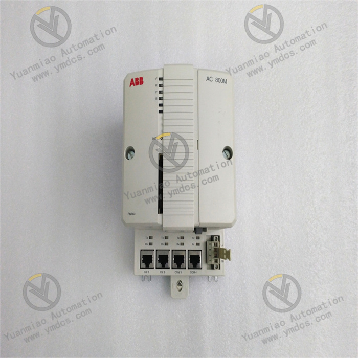
Rich Communication Interfaces: Provides multiple communication interfaces such as Ethernet and serial ports (e.g., RS-232C). The Ethernet interface connects to control networks for high-speed data transmission with other controllers, host computers, and monitoring systems. The serial port connects to specific configuration tools or other serial-enabled devices, enabling parameter setting and debugging.
High Reliability: Through rigorous testing and certification, it can operate stably in harsh industrial environments. For example, it adapts to a wide temperature range and has certain anti-vibration and anti-shock capabilities, meeting the mechanical stress requirements of heavy industry sites.
Flexible Configuration and Scalability: Supports multiple configuration methods and can be flexibly adjusted according to different application needs. It seamlessly integrates with other modules in the ABB 800xA system, facilitating system expansion and upgrading to adapt to control projects of varying scales and complexities.
Rich Communication Interfaces: Provides multiple communication interfaces such as Ethernet and serial ports (e.g., RS-232C). The Ethernet interface connects to control networks for high-speed data transmission with other controllers, host computers, and monitoring systems. The serial port connects to specific configuration tools or other serial-enabled devices, enabling parameter setting and debugging.
Technical Parameters
Power Supply Voltage: Typically supports wide voltage input of 110-240V; some sources indicate 24V DC power supply. Specifics shall be determined according to actual product specifications.
Communication Interfaces:
Communication Interfaces:
- 2× RJ45 Ethernet ports for control network connection;
- 2× RJ45 serial ports, one of which is an RS-232C port with modem control signals, and the other is isolated for connecting configuration tools.
Dimensions: Approximately 135mm (length) × 186mm (height) × 119mm (width), weighing about 1.2kg. Some sources show dimensions of 16cm×16cm×12cm and weight of 0.8kg, possibly differing by version or measurement method.
Operating Temperature: Generally -10°C to 50°C; storage temperature: -20°C to 70°C; humidity: 10% to 90% non-condensing.
Application Scenarios
Power Systems: Suitable for automation control in power plants, substations, etc., such as monitoring and controlling generators, transformers, and transmission lines. It realizes automated management of power production, transmission, and distribution to ensure stable operation and efficient power supply.
Petrochemical Industry: Used for automated control of various production units and processes in petrochemical production, such as temperature and pressure control of reactors, level and flow regulation of distillation columns, and safety interlock control of the entire production process. It ensures safe, stable, and efficient production, meeting the industry’s requirements for precise control and high reliability.
Water Treatment: Applied to automation control systems in water treatment plants to precisely control and monitor water purification, filtration, disinfection, and other processes. It achieves stable water quality compliance and energy-saving optimization of treatment processes, improving water treatment efficiency and quality.
Installation and Configuration Key Points
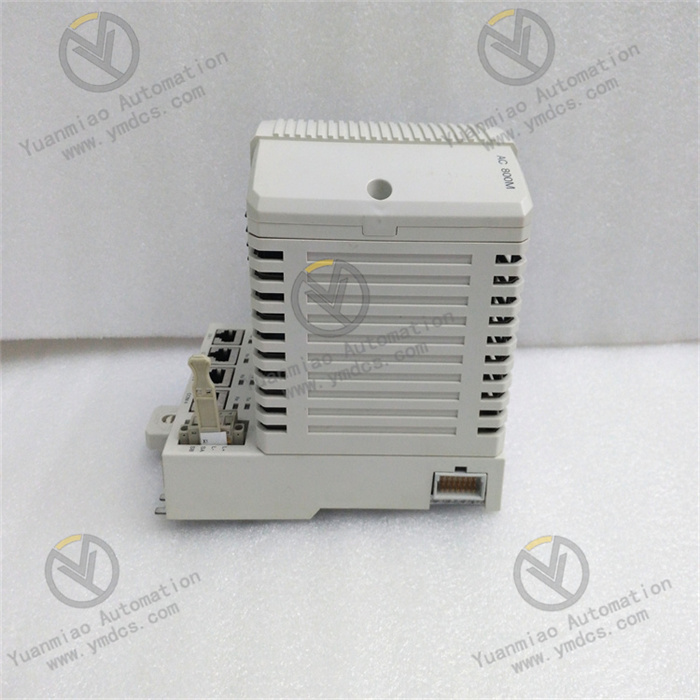
Installation: The module uses a standard DIN rail mounting method. Its unique sliding and locking mechanism enables easy installation and removal on the rail. When installing, choose a well-ventilated location away from strong electromagnetic interference sources, and reserve sufficient heat dissipation space to ensure normal heat dissipation during operation and prevent performance degradation or equipment damage due to overheating.
Configuration: Typically configured using ABB’s engineering tool software such as 800xA Control Builder. The software allows setting various module parameters, including communication parameters (e.g., Ethernet IP address, serial port baud rate), definition and mapping of input/output signals, and writing/downloading control algorithms. Through these configurations, the PM860K01 module integrates with other devices and systems to achieve complete automation control functions according to specific application needs.
Configuration: Typically configured using ABB’s engineering tool software such as 800xA Control Builder. The software allows setting various module parameters, including communication parameters (e.g., Ethernet IP address, serial port baud rate), definition and mapping of input/output signals, and writing/downloading control algorithms. Through these configurations, the PM860K01 module integrates with other devices and systems to achieve complete automation control functions according to specific application needs.
Troubleshooting Guide for ABB PM860K01 3BSE018100R1 Controller
I. Analysis of Hardware Indicator Status
The PM860K01 controller is typically equipped with status indicator lights (LEDs), through which basic faults can be quickly identified by light color and flashing patterns. Below are common indicator meanings and troubleshooting measures:
| Indicator | Normal Status | Abnormal Status and Possible Causes | Solutions |
|---|---|---|---|
| PWR (Power) | Green, steady on | - Off: Power not connected or power module failure - Flashing: Unstable power voltage or redundant power switching anomaly | 1. Check if 24 VDC power input is normal (measure with a multimeter) 2. Replace the power module or check terminal connections |
| RUN (Operation) | Green, periodic flashing | - Off: Controller not started or firmware damaged - Steady on: Program execution stagnation or deadlock | 1. Restart the controller 2. Re-download firmware or program via Control Builder M 3. Check for dead loops in program logic |
| ERR (Error) | Off | - Red, steady on: Hardware failure (e.g., memory, processor anomaly) - Red, flashing: Software error (e.g., configuration error, communication timeout) | 1. View system logs for specific error codes 2. Check I/O module wiring or communication bus 3. Contact technical support for hardware replacement |
| COM (Communication) | Green, flashing (data transmission) | - Off: Ethernet/PROFINET not connected - Red: Communication link failure (e.g., IP conflict, network cable damage) | 1. Check network cable connection and switch status 2. Confirm correct IP address and subnet mask configuration 3. Replace network cable or test port |
| FWD (Forward) | Green, flashing (bus communication) | - Off: Fieldbus (e.g., PROFIBUS) not activated - Red: Bus error (slave failure, missing terminating resistor) | 1. Check bus cable connection and terminating resistor (120Ω) 2. Investigate slave device faults 3. Re-configure bus parameters |
II. Common Fault Types and Troubleshooting Steps
1. Controller Fails to Start or Freezes
Possible Causes:
Possible Causes:
- Firmware damage or program errors
- Hardware failures (e.g., memory modules, processors)
- Power anomalies or loose wiring
Troubleshooting Steps:
- Power Check:
- Measure input voltage to ensure it is 24 VDC (±15%) and confirm normal operation of redundant power (if enabled).
- Inspect power terminals for looseness or oxidation; re-plug or replace terminals.
- Firmware/Program Recovery:
- Re-download official firmware via SD card or Control Builder M (must match hardware version).
- Attempt to load a default program (empty program) to rule out startup faults caused by user programs.
- Hardware Reset:
- Disconnect power, wait 30 seconds, and reconnect to observe if recovery occurs.
- If resetting multiple times fails, hardware failure is likely; contact ABB for replacement.
2. Communication Failures (Ethernet/PROFINET/Fieldbus)
Possible Causes:
Possible Causes:
- Incorrect network parameter configuration (IP address conflicts, duplicate bus addresses)
- Damaged or poorly connected communication cables, or shield failure
- Switch/gateway faults or protocol compatibility issues
Troubleshooting Steps:
- Ethernet/PROFINET Faults:
- IP Configuration: Use Control Builder M to confirm the controller IP is in the same subnet as the host computer/switch; disable firewalls or open necessary ports (e.g., 80, 4840).
- Physical Connection: Replace with CAT5e/CAT6 shielded network cables and test switch ports (verify by connecting a laptop).
- Device Name: For PROFINET, ensure the controller device name is unique and matches the configuration (check via ABB Tool or network scanning tools).
- PROFIBUS/CANopen Fieldbus Faults:
- Terminating Resistor: Check if 120Ω terminating resistors are connected at both ends of the bus and if master/slave addresses are duplicated (e.g., PROFIBUS slave addresses must be unique).
- Bus Load: Confirm the number of slaves does not exceed the bus capacity; use an oscilloscope to check bus signal waveforms for normality (no noise or attenuation).
- Module Compatibility: Ensure I/O module firmware versions are compatible with the controller; update module firmware via Control Builder M.

3. Unresponsive or Abnormal Data in I/O Modules
Possible Causes:
- Incorrect I/O module wiring (e.g., reverse power polarity, short circuit)
- Module address configuration errors or hardware damage
- Interrupted bus communication or signal interference
Troubleshooting Steps:
- Wiring Check:
- Confirm input/output signal types (voltage, current) match module specifications per drawings, avoiding high-voltage (e.g., 220V) connections to low-voltage modules.
- Use a multimeter to measure input signals for normality (e.g., voltage change when a button is pressed) and check for voltage/current output in output modules.
- Configuration Verification:
- In Control Builder M, check that I/O module models and addresses match actual hardware; rescan the bus and download configurations.
- Test individual modules by removing other modules and connecting only the target module to rule out excessive bus load issues.
- Anti-Interference Measures:
- Ensure I/O cables are routed separately from power cables (spacing ≥30 cm); use twisted shielded cables with reliable grounding (single-end shielding grounding).
- Check if the control cabinet grounding meets EMC standards (ground resistance ≤10Ω).
4. System Redundancy Failure (e.g., Dual Power Supply, Controller Redundancy)
Possible Causes:
Possible Causes:
- Faulty redundant power modules or incorrect wiring
- Incorrect redundant controller configuration or synchronization failure
Troubleshooting Steps:
- Redundant Power Test:
- Disconnect the main power supply and observe if the redundant power supply switches automatically, with the controller RUN light flashing normally and no ERROR alarms.
- Check for loose connections between redundant power modules and replace faulty modules.
- Controller Redundancy Configuration:
- Confirm correct installation of redundant firmware; configure redundancy pairs and synchronize programs via Control Builder M.
- Simulate main controller failure (e.g., power off) to observe if the slave controller takes over automatically and if data remains consistent (no loss or corruption).
5. Abnormal Program Operation or Logic Errors
Possible Causes:
Possible Causes:
- Syntax errors, dead loops, or resource conflicts in user programs
- Improper real-time operating system (RTOS) task priority configuration
- Input/output signal delays or excessively long scan cycles
Troubleshooting Steps:
- Program Debugging:
- Use Control Builder M’s online monitoring function to debug programs line by line and check if variable values meet expectations.
- Comment out program segments and enable function blocks step-by-step to locate abnormal code (e.g., improper PID algorithm parameters, timer overflows).
- Task Configuration Optimization:
- View the RTOS task list in the software to ensure high-priority tasks (e.g., emergency shutdown) are not blocked by low-priority tasks.
- Adjust scan cycles (e.g., shorten cyclic task cycles) to avoid control delays due to processing lags.
- Resource Check:
- Confirm memory and CPU utilization do not exceed thresholds (view via controller diagnostic interface); delete redundant library files or unused variables.