Description
Functional Characteristics
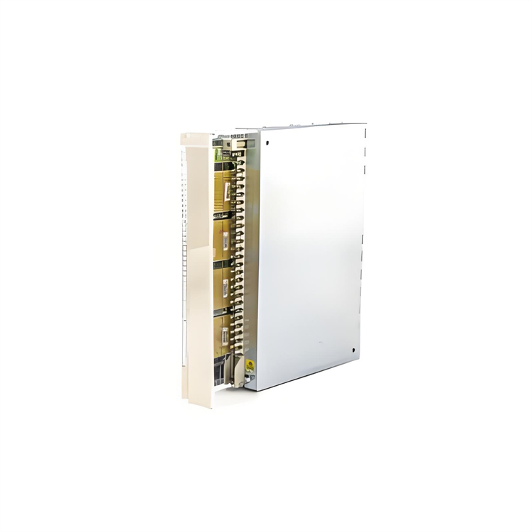
Rugged Design: Withstands harsh industrial environments, offering long-term durability and stable performance.
Safety Integration: Fully compatible with TRICONEX SIS, enhancing overall system safety and reliability.
Fast Response: Provides rapid and precise digital input processing, crucial for timely decision-making in control applications.
Diagnostic Capability: Equipped with advanced diagnostic functions for real-time monitoring and fault troubleshooting.
Technical Specifications
Input Voltage Range: Accepts a wide range of input voltages to ensure compatibility with various digital signals.
Response Time: Optimized for fast response, critical for real-time control and safety applications.
Isolation: High isolation between channels prevents interference and ensures signal integrity.
Power Supply: Uses standard industrial power to ensure stable and reliable operation.
Operating Temperature: Functions in a temperature range of -40°C to +70°C, suitable for diverse industrial environments.
Shock and Vibration Resistance: Complies with industrial shock and vibration standards for reliable operation under harsh conditions.
Dimensions and Weight: Compact design for easy installation in control panels and cabinets.
Compliance: Meets international safety and compliance standards for use in critical control environments.
Application Cases
Power Industry: In power plants, this module monitors the operational status of generator sets by collecting digital signals such as generator speed signals, circuit breaker opening/closing signals, and protection device action signals, enabling timely fault detection and corresponding protective measures. In power system substations, the TRICONEX DI2301 collects status signals of various switching devices and protection device output signals, enabling real-time monitoring and control of substation operations to ensure safe and stable power system operation.
Chemical Industry: Chemical production involves many risk factors and requires extremely high safety control. The TRICONEX DI2301 collects various digital signals in chemical production units, such as temperature and pressure alarm signals from reactors, valve switch signals on material transport pipelines, and alarm signals from combustible and toxic gas detectors. The safety instrument system processes and evaluates these signals, and when anomalies occur, it promptly implements safety measures such as emergency shutdown and material supply cutoff to prevent accidents and their escalation.
Steel Industry: In steelmaking and ironmaking processes of steel plants, the TRICONEX DI2301 monitors and controls the operational status of various equipment. For example, it collects digital signals such as blast furnace level signals, hot stove combustion control signals, converter tilting signals, and continuous casting machine straightening machine speed signals to achieve automated control and safety protection of steel production processes, improving production efficiency and product quality while ensuring safe and reliable production.
Installation and Commissioning Guide for TRICONEX DI2301
Installation Guide
Installation Environment Check: Select an installation environment that meets product requirements, with an ambient temperature within the specified operating range (typically -40°C to 85°C) and relative humidity of 5% to 95% (non-condensing). Ensure the installation location is stable, vibration-free, away from strong electromagnetic interference and heat sources, and avoid damp, dusty, or corrosive gas environments.
Module Installation: The TRICONEX DI2301 typically uses DIN rail mounting. Securely clip the module onto the DIN rail and fasten it with rail clamps or screws to prevent looseness during operation. When installing in a control cabinet, maintain spacing between modules for heat dissipation and maintenance.
Wiring: Connect the DI2301's power and signal lines correctly according to system requirements and the module's wiring diagram. Ensure stable power supply within the module's rated voltage (typically 24VAC). Use shielded cables for signal inputs to reduce electromagnetic interference, with reliable grounding of the shield layer. Insert wires into corresponding terminal blocks and tighten screws to ensure secure connections and prevent poor contact.
Commissioning Guide
Power Test: Apply power to the module and use a multimeter to measure the power voltage within the rated range. Observe the module's power indicator light; if it does not light or flashes abnormally, check the power circuit or the module's power input section.
Input Signal Test: Apply different digital signals to the DI2301 (e.g., via external switch signal sources or other devices) and check if the module correctly receives and identifies them. Use the module's diagnostic functions or monitoring software to view input signal status and values, ensuring accurate conversion of input signals to digital quantities and transmission to the system for processing.
Communication Test: If the DI2301 needs to communicate with other devices (e.g., main controllers or host computers), test communication parameters (protocol, baud rate, data bits, stop bits). Verify normal communication and accurate data transmission by sending and receiving test data.
Function Test: Conduct corresponding function tests based on the module's role in the system. For example, if monitoring equipment status, check if it promptly and accurately reflects equipment state changes; if used for safety interlock control, verify correct output of control signals under different safety conditions to ensure system safety.
System Integration Test: After individual module commissioning, integrate the DI2301 with the entire system. Observe its operation and coordination with other modules/devices, and adjust parameters if necessary to optimize overall system performance.
Common Faults and Solutions for TRICONEX DI2301 Module
1. Module Power Failure
- Module indicator lights (e.g., PWR) are off.
- System alarms prompt "abnormal module power supply."
Possible Causes: - Loose, disconnected, or poor power connections.
- Power voltage outside the module's rated range (e.g., too low, too high, or fluctuating).
- Internal module power circuit damage.
Solutions: - Check Power Connections: Ensure power cables are securely connected, free of looseness, oxidation, or breaks; re 插拔 or replace cables if needed. Verify tight power terminal blocks and measure input voltage with a multimeter to meet specifications (e.g., DC 24V ±10%).
- Test Power Stability: Use a regulated power supply or oscilloscope to detect voltage fluctuations and ensure stability within allowable ranges.
- Replace Module or Power Supply: If internal power damage is confirmed, replace the module; if it's a system power issue, replace the power supply module.
2. Abnormal Input Signals (No Signal or False Alarms)
- Module indicator lights (e.g., channel status lights) do not change when external switch signals (e.g., buttons, sensors) actuate.
- Module channel status contradicts actual signal status (e.g., shows "on" when disconnected, or vice versa).
Possible Causes: - Loose, shorted, or open input signal wires.
- Mismatched signal type and module configuration (e.g., DC/AC signal, voltage level error).
- Faulty external devices (e.g., sensors) or abnormal outputs.
- Damaged module channels or incorrect configuration parameters (e.g., input type, filter time settings).
Solutions: - Check Signal Wiring: Measure signal terminal voltage with a multimeter to confirm signal presence (e.g., DC 24V). Inspect cables for damage, shorts, or poor contact; replace faulty cables or terminals.
- Verify Signal Compatibility: Ensure the module supports the signal type (e.g., DI2301 typically uses DC input) and matches external signal voltage levels (e.g., 24V DC).
- Test External Devices: Short the module's input terminals directly and observe indicator changes; if normal, the external device (e.g., sensor) is faulty and needs replacement.
- Check Module Configuration: Use system configuration software (e.g., Triconex Tricon Explorer) to confirm correct channel parameter settings (e.g., input type, filter time); re-download the configuration or reset the module.
- Replace Faulty Channels or Module: If a single channel is damaged, use a spare channel; if multiple channels are abnormal, replace the module.

3. Communication Failure (Module Disconnected from System)
- The system cannot recognize the module (e.g., shows "offline" or "fault" in configuration).
- Abnormal flashing or 熄灭 of communication indicator lights (e.g., COM light).
Possible Causes: - Poor contact or damage to communication cables (e.g., backplane bus, Ethernet cables).
- Incorrect module address settings (e.g., conflicts with other modules).
- Backplane bus faults or poor card slot contact.
- Incompatible module firmware version with the system.
Solutions: - Check Communication Connections: Re 插拔 the module to ensure good backplane bus contact; inspect communication cables for firmness, and replace cables or test other slots.
- Verify Module Address: Confirm unique addresses via module DIP switches or configuration software, with no duplicates or out-of-range values (refer to the module manual).
- Update Firmware or Restart System: Check module firmware version; if incompatible, contact the manufacturer for updates. Restart the controller or module to clear temporary communication faults.
- Replace Backplane or Module: If the backplane bus is faulty, replace the backplane; if communication issues persist, replace the module.
4. Abnormal Indicator Lights (Unintended Status)
- Status indicator lights (e.g., OK, FAULT) are constantly on or flash abnormally, inconsistent with normal operation.
Possible Causes: - Internal hardware faults (e.g., damaged chips, bulging capacitors).
- Overheating or environmental interference (e.g., EMI causing false alarms).
- Firmware errors or logic configuration errors.
Solutions: - Physical Module Inspection: Power off and check for visible damage (e.g., swollen capacitors, burnt chips); replace the module if found. Ensure good ventilation in the installation environment, away from high temperatures or strong electromagnetic interference (keep away from power cables).
- Reload Configuration or Reset Module: Re-download the logic configuration via system software or reset the module (follow manual steps).
- Replace Module: If indicator abnormalities persist, it may be a permanent hardware fault requiring module replacement.