Description
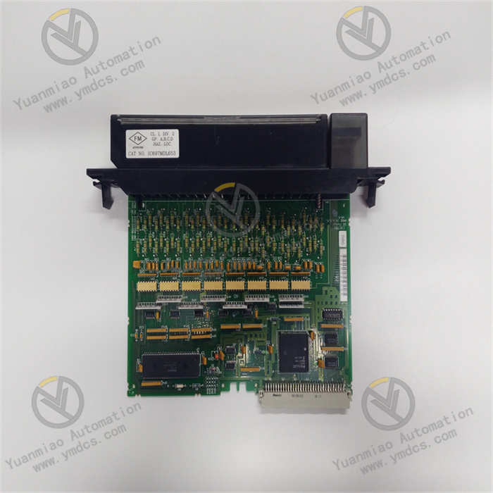
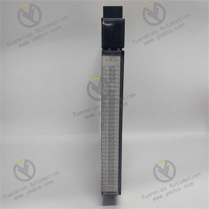
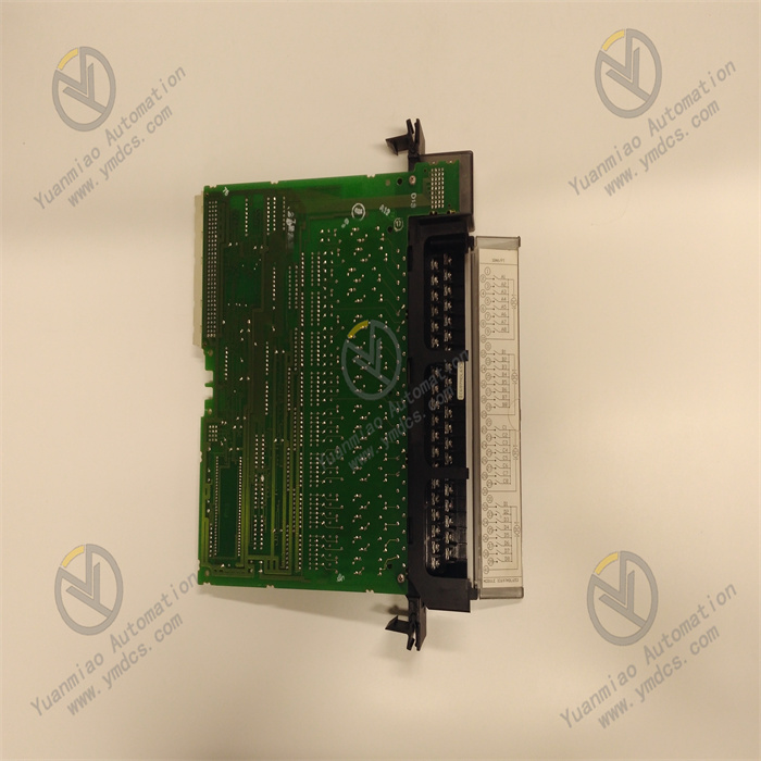
GE IC697MDL653
I. Product Overview
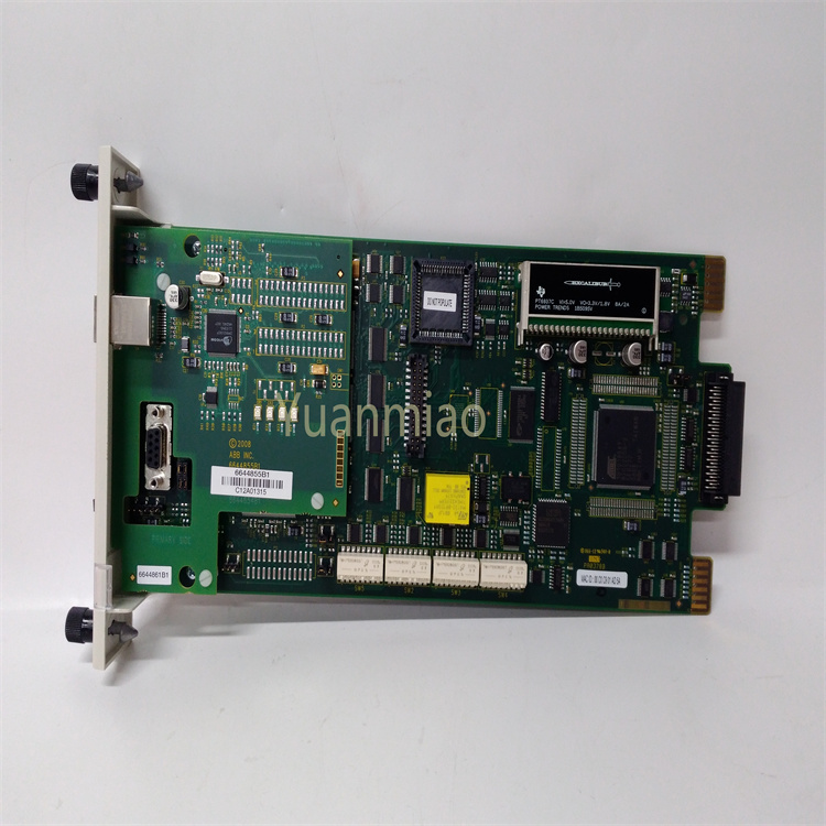
GE IC697MDL653 is a high-performance discrete input module belonging to the GE Fanuc Series 90-70 PLC system, with extensive and important applications in the field of industrial automation. It is mainly used to receive various discrete signals from industrial sites, such as switch signals from buttons, limit switches, proximity switches and other devices, which can be accurately captured by it. After being processed by the module, these signals are transmitted to the central processing unit (CPU) of the PLC, providing a key basis for the CPU to make logical judgments and control decisions. It is an indispensable signal acquisition link in industrial automation control systems, ensuring the system's real-time monitoring and precise control of on-site equipment status, and is widely used in many industrial scenarios such as manufacturing production lines, mechanical processing equipment, and warehousing and logistics systems.
II. Technical Parameters
(I) Input Parameters
- Number of Input Points: It has 32 discrete input points, which can connect 32 different discrete signal sources at the same time. It can meet the needs of collecting status signals of multiple devices in medium and large-scale industrial sites, reducing the number of modules used, and lowering system costs and wiring complexity.
- Input Voltage Range: It supports 12-24V DC input voltage. This wide voltage range design enables it to adapt to various common industrial DC power supplies, enhancing compatibility in different power supply environments. There is no need to configure a separate power supply for a specific voltage, improving the versatility of the module.
- Input Current: The rated input current of each input point is 7mA. This parameter ensures that the module can respond sensitively when receiving signals without consuming too much power, reducing the overall power consumption of the system while ensuring the accuracy of signal acquisition.
(II) Response Time
The maximum response time of the input signal is 1ms. The extremely fast response speed enables the module to quickly capture changes in the status of on-site equipment, ensuring the real-time performance of signal acquisition. This feature is particularly important in industrial scenarios with high requirements for equipment action response, such as material detection in high-speed production lines, which can avoid control errors caused by signal delay.
(III) Electrical Isolation
The module adopts a 250V AC electrical isolation design. This isolation method can effectively resist the impact of adverse factors such as electromagnetic interference and voltage fluctuations in industrial sites on the normal operation of the module, prevent external interference signals from entering the PLC system, ensure the accuracy of signal acquisition and the stability of the module operation, and at the same time improve the safety of the module and the entire control system, reducing the probability of failures caused by electrical interference.
(IV) Working Environment
- Operating Temperature: It can work normally in an ambient temperature of 0°C-60°C, and can adapt to the common temperature change range in industrial sites. It can operate stably whether in hot workshops in summer or workshops with low temperatures in winter.
- Relative Humidity: It can withstand a relative humidity environment of 5%-95% (non-condensing). In humid industrial environments, such as food processing workshops and near washing equipment, it can also maintain a good working state, and its performance will not be affected by humidity issues.
(V) Installation and Dimensions
- Installation Method: It adopts a standard rack mounting method, which is perfectly compatible with other modules of the GE Fanuc Series 90-70 PLC system. The installation process is simple and convenient, and it can be quickly integrated into the control system, improving the efficiency of system construction.
- Module Dimensions: It conforms to the series standard dimensions, with a width of [X] mm, a height of [X] mm, and a depth of [X] mm (the specific dimensions are subject to the actual product). The compact structure design saves the installation space in the control cabinet, facilitating the arrangement and wiring of modules.
III. Functional Features
(I) Efficient Signal Acquisition Capability
With 32 input points and a fast response time of 1ms, GE IC697MDL653 can efficiently and timely collect multiple discrete signals in industrial sites. Whether receiving status signals from multiple devices at the same time or capturing rapid action changes of devices, the module can accurately respond, ensuring that the CPU can obtain comprehensive and accurate on-site information in real-time, providing strong support for the precise control of the control system. For example, in an automated assembly production line, sensor signals from multiple stations can be transmitted to the CPU through this module at the same time, enabling the CPU to timely grasp the working status of each station and coordinate the actions of each link.
(II) Strong Anti-Interference Ability
The 250V AC electrical isolation design is the core guarantee of its anti-interference ability. There are often a large number of electromagnetic devices in industrial sites, such as motors and transformers. These devices will generate strong electromagnetic interference, which may easily lead to signal transmission distortion or module misoperation. The electrical isolation function of this module can effectively block the propagation path of interference signals, enabling the module to work stably in complex electromagnetic environments, ensuring that the collected signals are true and reliable, and greatly improving the anti-interference performance of the entire control system.
(III) Good Compatibility and Integratability
As a member of the GE Fanuc Series 90-70 PLC system, IC697MDL653 has excellent compatibility with other modules in the system, such as CPU modules, output modules, communication modules, etc. When building a control system, various modules can be flexibly matched according to actual needs to realize the expansion and integration of system functions. At the same time, the standard rack mounting method enables it to quickly integrate into the system architecture, simplifying the system design and installation process, and reducing the difficulty of system integration.
(IV) Reliable Working Performance
The module is manufactured with industrial-grade components and has undergone strict quality inspection and environmental testing, with extremely high reliability and stability. It can work continuously and stably in the temperature range of 0°C-60°C and relative humidity of 5%-95%, and can adapt to harsh working conditions in industrial sites, reducing production interruptions caused by module failures and improving the continuity and efficiency of industrial production.
(V) Convenient Status Indication
The module is equipped with intuitive LED status indicators, and each input point corresponds to an indicator. When the input point receives a valid signal, the corresponding indicator will light up. Operators can quickly judge the working status of each input point through the indicators, which is convenient for system debugging, fault Investigation and daily maintenance. During the operation of the system, if a certain input point fails, the problem can be quickly located through the status of the indicator, shortening the fault handling time.
IV. Operation Guide
(I) Installation Steps
- Preparation Before Installation: First, carefully inspect the appearance of the module to ensure there is no physical damage such as shell damage, bent or loose pins. Prepare the required installation tools, such as screwdrivers, wrenches, etc., as well as supporting installation accessories such as racks and guide rails. At the same time, clean the inside of the control cabinet at the installation location to ensure there is no dust, debris or water accumulation, and ensure that the installation environment meets the working conditions of the module, that is, the temperature is 0°C-60°C and the relative humidity is 5%-95% (non-condensing). In addition, be sure to cut off the main power supply of the control cabinet to prevent electric shock accidents during installation.
- Module Installation: Fix the rack or guide rail at a suitable position in the control cabinet, then insert the GE IC697MDL653 module into the corresponding slot of the rack or guide rail smoothly according to the installation direction of the module, ensuring that the module is closely attached to the rack or guide rail without looseness. Then, use screws to firmly fix the module on the rack or guide rail to prevent the module from shifting or falling off due to vibration during equipment operation, which may affect signal acquisition and system stability.
- Wiring Connection: Refer to the wiring diagram of the module, connect the discrete signal cables from the on-site equipment to the input terminals of the module. When wiring, pay attention to distinguishing the positive and negative polarities (if any), ensure that the cables are connected firmly and in good contact, and avoid virtual connections, short circuits, etc. Each input point corresponds to a specific terminal, which must be connected correctly according to the actual situation of the signal source, and must not be connected incorrectly. After wiring is completed, check again whether the wiring is correct and firm. After confirming that it is correct, arrange the cables neatly to avoid messy cables affecting subsequent operations or causing failures.
(II) Configuration and Debugging
- Software Configuration: Install the programming software corresponding to the GE Fanuc Series 90-70 PLC system, such as VersaPro. Open the software, create a new project, and add the IC697MDL653 module to the project. Set the parameters of the module according to the module model and actual hardware configuration, such as the type of input signal (NPN or PNP, selected according to the actual equipment situation). After completing the parameter configuration, download the configuration information to the CPU of the PLC so that the CPU can correctly identify and communicate with the module.
- Signal Testing: After completing the installation and configuration, turn on the power of the control cabinet to supply power to the module and the entire PLC system. Operate the discrete signal sources on site one by one, such as pressing buttons, triggering limit switches, etc., and observe whether the corresponding LED indicators on the module light up. If the indicator lights up normally, it means that the module can correctly receive the input signal. In addition, through the online monitoring function of the programming software, check whether the signal status uploaded by the module to the CPU is consistent with the actual on-site status, and verify the accuracy of signal transmission.
- Troubleshooting: If it is found that the indicator of a certain input point is not on or the signal status is inconsistent with the actual situation, first check whether the wiring of the input point is loose, falling off or connected incorrectly. Re-tighten or correct the wiring and test again. If the wiring is normal, the signal source device can be replaced or the input point of the module can be replaced for testing to determine whether it is a signal source fault or a module input point fault. If multiple input points have problems, check whether the power supply of the module is normal, whether the module is installed in place, whether the parameter configuration is correct, etc., and gradually 排查 and repair the fault causes.
(III) Operation and Maintenance
- Daily Operation Monitoring: During the normal operation of the system, regularly observe the status of the LED indicators on the module to ensure that the indicators of each input point can light up and go off normally according to changes in on-site signals. Through the programming software or upper computer monitoring system, monitor the signal status uploaded by the module in real-time to find abnormal situations in time. At the same time, pay attention to the working environment temperature and humidity of the module to ensure that they are within the specified range, avoiding the impact of environmental factors on the module performance.
- Regular Maintenance: Clean the module regularly, wipe the dust on the module surface with a dry soft cloth to prevent excessive dust accumulation from affecting the heat dissipation of the module or causing electrical faults. Check whether the module is installed firmly, and whether the wiring terminals are loose, oxidized, etc. If so, tighten or handle them in time. Regularly test the electrical performance of the module, such as measuring the voltage and resistance of the input points with a multimeter to ensure that the module performance is normal.
- Fault Handling: When the module fails, such as being unable to collect signals, abnormal indicators, etc., the power supply of the module should be cut off first to avoid expanding the fault. Then, according to the troubleshooting steps, check the wiring, power supply, parameter configuration and other aspects step by step to determine the cause of the fault. If it is a fault of the module itself, the spare module should be replaced in time to ensure the normal operation of the system. The replaced faulty module can be handed over to professionals for repair or scrapped.


