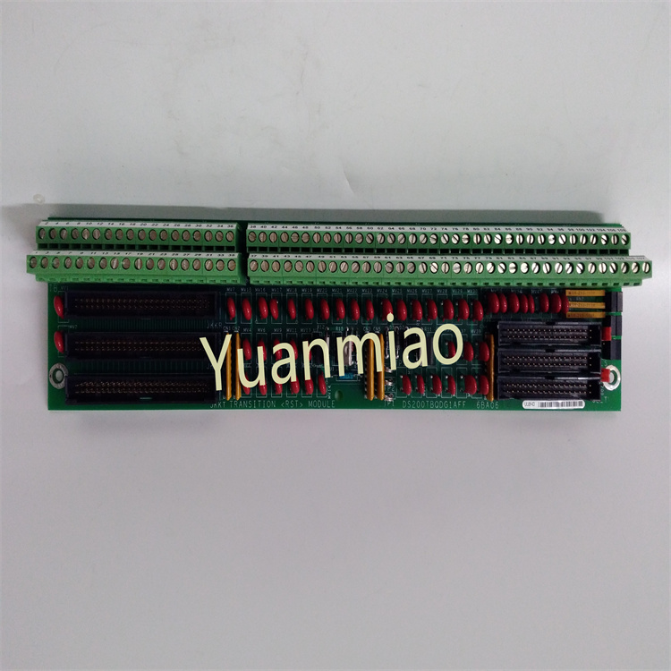
Description
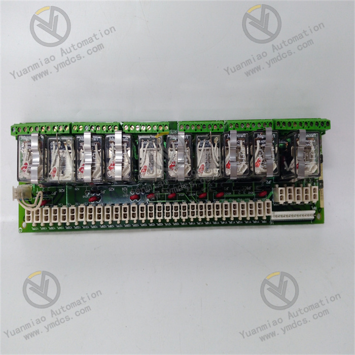
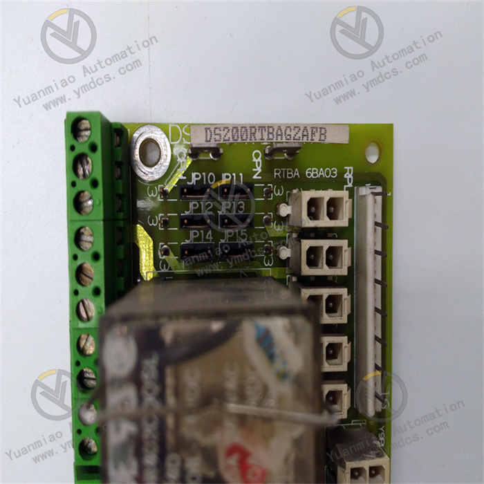
The GE DS200RTBAG2AFB is a printed circuit board, and its specific function is to serve as a relay terminal board. It provides connection interfaces for the relays in the system, enabling the relays to make electrical connections with other components, thus achieving the control of various devices. For example, it can control the relevant equipment of gas turbines or steam turbines. Through this relay terminal board, control signals can be transmitted to the corresponding relays, and then the opening and closing states of the relays can be controlled, playing a crucial role in signal transmission and control in the entire control system. It ensures that the Mark V Speedtronic system can operate stably and reliably, and enables precise control of industrial equipment. Functional Features Relay Control: There are ten relays on the board, which are divided into two types: DPDT (Double Pole Double Throw) and 4PDT (Four Pole Double Throw). Among them, there are seven DPDT relays. Each relay has two C-type contacts, the contact charge is 10A, and the coil is 110VDC. There are three 4PDT relays. Each relay has four contacts, the contact charge is 1A, and the coil is also 110VDC. Protection Function: The 130VAC metal oxide varistor (MOV) can protect all the on-board relays, enhancing the reliability and stability of the equipment. Expandability: This card can be used together with various GE exciters and drivers in the cabinet. It can control remote and LAN I/O terminals, facilitating system expansion and integration.
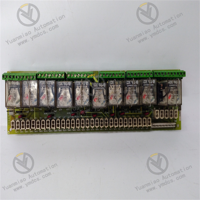
Technical Specification Parameters Relay Type: Includes DPDT and 4PDT relays. Relay Contact Parameters: The contact charge of the DPDT relay is 10A, and the contact charge of the 4PDT relay is 1A. Relay Coil Voltage: 110VDC. Protection Component: 130VAC metal oxide varistor. Application Areas: It is mainly applied in relevant fields such as GE's Mark V Speedtronic steam turbine control system, used to achieve functions such as signal transmission, conversion, and relay control, ensuring the stable operation and precise control of the system. In industries such as power, petrochemical, and metallurgy, this relay terminal board may be used in the control systems of large rotating equipment such as steam turbines, compressors, and fans. For example, in the control of steam turbines in the power industry, it can be used to control the transmission and control of signals such as the start and stop of relevant equipment and speed regulation.
Common Faults and Solutions Relay Faults: Possible reasons include burned-out relay coils, worn contacts, etc. The solution is to check the working status of the relays, use tools such as a multimeter to measure the coil resistance and the on-off condition of the contacts. If faulty relays are found, replace them with relays of the same model in a timely manner. Communication Faults: They may be caused by poor communication line connections, incorrect communication protocol settings, etc. The solution is to check whether the communication lines are loose or damaged, and ensure reliable connection. Check and verify the communication protocol settings to ensure consistency with other devices. Power Supply Faults: They may be caused by abnormal power input, damaged power modules, etc. The solution is to check whether the power input voltage is within the specified range. If the power module is damaged, contact professional maintenance personnel for repair or replacement.
How to diagnose the faults of DS200RTBAG2AFB? Appearance Inspection Check whether there is obvious physical damage on the surface of the printed circuit board, such as burned components, bulging capacitors, broken circuits, loose soldering points, etc. These problems may cause the circuit board to fail to work properly or result in intermittent faults. Check whether there is dust or debris accumulation, which may affect the heat dissipation of the circuit board or lead to problems such as short circuits. Electrical Connection Inspection Ensure that all the cables connected to the DS200RTBAG2AFB are firmly connected without signs of looseness, oxidation, or damage. Loose connections may lead to unstable signal transmission or interruptions. Check whether the power connection is normal and measure whether the input power voltage is within the specified range. If the power voltage is abnormal, it may cause the circuit board to work improperly. System Status Inspection Check the operation status indicator lights of the Mark V Speedtronic system to determine whether there are fault indications related to the DS200RTBAG2AFB. Some systems may prompt the type of fault through specific indicator light flashing patterns. Check the system's alarm information and log records to see if there are error codes or fault descriptions related to this circuit board. This information can help locate the problem. Function Test Use professional testing equipment such as a multimeter and an oscilloscope to measure the key signal points on the circuit board. For example, check whether the driving signal of the relay is normal, and whether the level of the input and output signals meets the requirements. Some actual working scenarios can be simulated. By inputting different control signals to the circuit board, observe whether its output meets the expectations. For example, trigger the action of the relay and check whether the corresponding contacts are correctly closed and opened.