Description
ABB EI813F 3BDH000022R1
I. Basic Information
Brand: ABB
Model: EI813F 3BDH000022R1
Naming Convention:
Model: EI813F 3BDH000022R1
Naming Convention:
- EI: Following ABB's traditional naming logic, E typically stands for Extension Module, and I for Input Module, meaning Input Extension Module.
- 813: Presumed to be a Digital Input Module (DI Module) (comparing EI802F as digital input and EI803F possibly as analog input, "813" may represent the number of channels, voltage type, or upgraded version).
- 3BDH000022R1: ABB product serial number used to identify the specific hardware version (R1 denotes the first revision).
Type: Digital Input Module (DI Module), used to collect switching signals (e.g., ON/OFF states) from industrial field devices.
Application Scenarios: Compatible with distributed control systems (DCS) or PLC systems of ABB AC 800M, AC 500-S and other controllers, commonly used in industrial automation, power, process control and other fields.
II. Physical Characteristics
Dimensions: Referencing similar products (e.g., EI802F), approximately 120mm×80mm×35mm (compact design suitable for standard industrial control cabinet installation).
Weight: Approximately 0.15-0.2kg (lightweight for easy on-site deployment).
Mounting Methods:
Weight: Approximately 0.15-0.2kg (lightweight for easy on-site deployment).
Mounting Methods:
- DIN rail mounting (supports quick disassembly and installation).
- Hot-swapping: Supported by some models (subject to specific specifications).
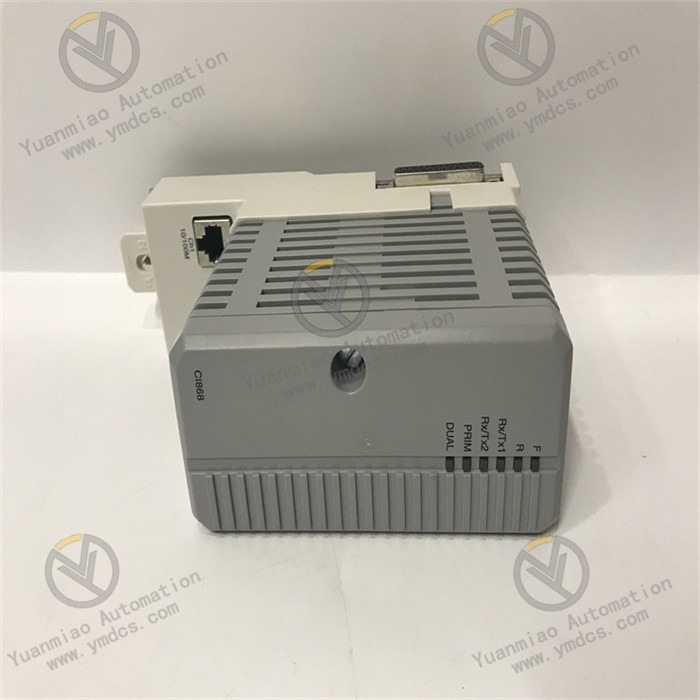
Indicators: - Power Indicator (PWR): Shows the module's power supply status.
- Channel Status Indicators: An LED for each channel to display the real-time signal input status (e.g., illuminated indicates signal conduction).
- Fault Indicator (FAULT): Alerts to module communication or hardware anomalies.
III. Electrical Characteristics
Power Supply Voltage: 24V DC (industrial standard power supply, supporting redundant power input for enhanced reliability).
Power Consumption: Approximately 1-2W (low-power design to reduce overall system energy consumption).
Number of Input Channels:
Power Consumption: Approximately 1-2W (low-power design to reduce overall system energy consumption).
Number of Input Channels:
- Presumed to be 16 channels (similar EI802F has 16 channels, and EI813F may continue this configuration).
- Supports dry contact (mechanical switches, relay contacts) or wet contact (24V DC level signals) inputs.
Electrical Isolation: - Isolation between channels or groups (e.g., optocoupler isolation) with strong electromagnetic interference (EMI) resistance to prevent signal crosstalk.
- Isolation voltage: Typically 250V AC/DC (ensuring safety and reliability).
Input Signal Types: - Dry contacts: Non-powered switch contacts (e.g., buttons, limit switches).
- Wet contacts: Powered level signals (e.g., 24V DC proximity switch outputs).
Response Time: - Configurable signal filtering time (e.g., 1-20ms to eliminate mechanical contact bounce).
IV. Environmental Requirements
Operating Temperature: -25°C ~ +60°C (industrial-wide temperature design for high and low-temperature environments).
Storage Temperature: -40°C ~ +85°C.
Relative Humidity: 5% ~ 95% (non-condensing), with dust and moisture resistance.
Protection Level: IP20 (requires installation in control cabinets to prevent dust and splashes).
Vibration/Shock Resistance: Complies with IEC 61326 standards, adapting to mechanical vibration environments in industrial sites.
V. Communication and Functions
Communication Protocols:
- Supports ABB FIELDBUS (direct communication with AC 800M/AC 500-S controllers).
- Can be extended to support fieldbuses such as Profibus DP and Ethernet/IP via gateway modules (additional configuration required).
Data Transmission: - Real-time conversion of input signals (0/1 states) into binary data, transmitted to the controller CPU via the backplane bus.
Diagnostic Functions: - Channel status monitoring (e.g., signal valid/invalid).
- Open-circuit detection, power failure alarms, communication link diagnostics.
- Fault codes reported to the monitoring system (e.g., ABB Control Builder) via the controller.
Functional Extensions: - Supports Sequence of Events (SOE) recording (for some models), accurately logging signal change times (millisecond-level resolution).
- Redundant configuration (requires matching redundant controllers and bus modules).
VI. Working Principle
Signal Acquisition:
- Receives switching signals from field devices via terminal modules (e.g., TB series), which enter the module after filtering.
Signal Conditioning: - Converts input signal levels (e.g., converts 24V DC signals to internal logic levels) and isolates external interference via optocouplers.
Analog-to-Digital Conversion: - Digital signals require no analog conversion and are directly encoded into binary data (e.g., "1" for conduction, "0" for disconnection), stored in registers.
Data Communication: - Transmits data to the controller via the module's internal bus, which executes corresponding actions (e.g., alarms, interlock controls) based on preset logic.
Self-Test and Alarm: - Periodically detects power, channel, and communication status, alarming via LED indicators and system logs in case of anomalies.
VII. Typical Application Scenarios
Industrial Automation:
- Monitoring start/stop status of production line equipment, detecting safety door switches, and collecting sensor signals (e.g., photoelectric switches, magnetic switches).
Power Systems: - Feedback on the position status of circuit breakers and disconnectors, monitoring switch status in power distribution cabinets.
Process Control: - Collecting valve switch status, motor operation/fault signals, and high/low level alarm inputs for storage tanks.
Mechanical Engineering: - Accessing machine tool limit protection signals, robot IO signal interaction, and equipment safety interlock signals.
VIII. Common Faults and Troubleshooting
| Fault Type | Possible Causes | Troubleshooting Methods |
|---|---|---|
| No Power to Module | 1. Loose or disconnected power wiring 2. Faulty power adapter 3. Blown internal fuse | 1. Check power connection 2. Replace power adapter 3. Contact technicians for module repair |
| Communication Interruption | 1. Damaged or poorly connected bus cable 2. Module address conflict 3. Incorrect communication protocol configuration | 1. Test bus cable continuity 2. Ensure unique module address 3. Check baud rate, slave address, etc. |
| No Signal in Channel | 1. Faulty external switch 2. Loose terminal wiring 3. Damaged channel optocoupler | 1. Measure switch continuity with a multimeter 2. Tighten terminal screws 3. Replace channel or module |
| False Signal Reporting | 1. Signal interference (unshielded cables or poor grounding) 2. Too short filtering time 3. Aging components with leakage | 1. Check if wiring is away from high-power equipment 2. Increase filtering time 3. Test channel insulation resistance |
| Module Overheating | 1. Inadequate ventilation in the installation environment 2. Internal component short circuit 3. Long-term full-load operation | 1. Add cooling fans 2. Inspect component appearance (e.g., bulging capacitors) after power-off 3. Optimize system |