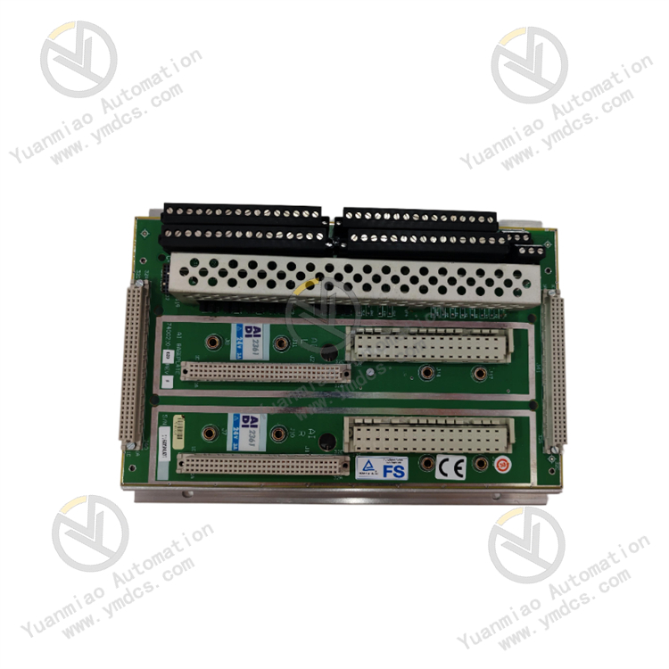
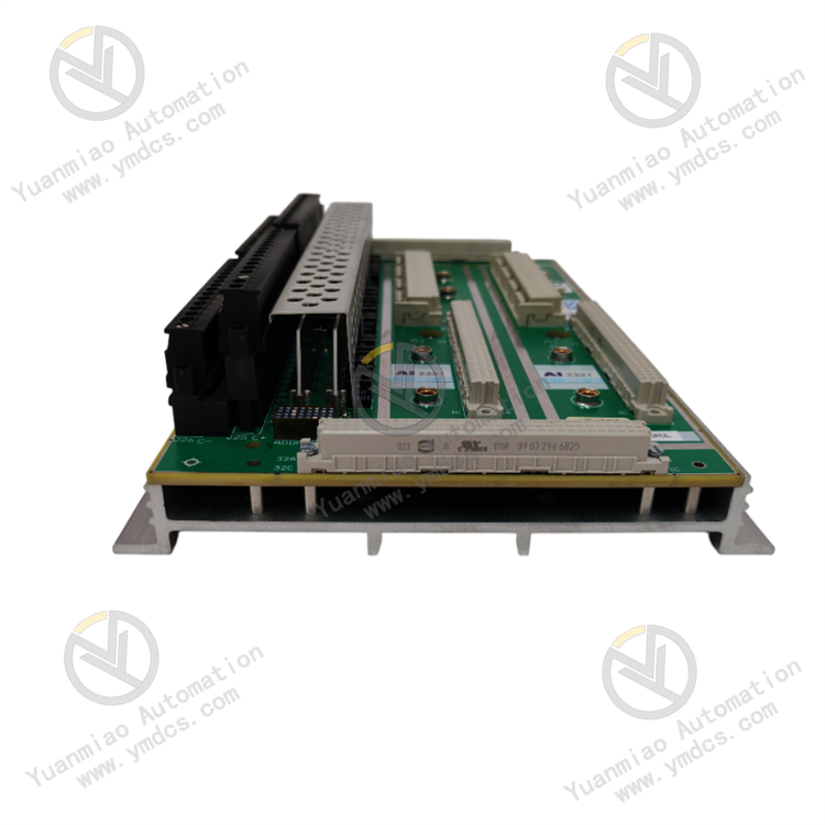
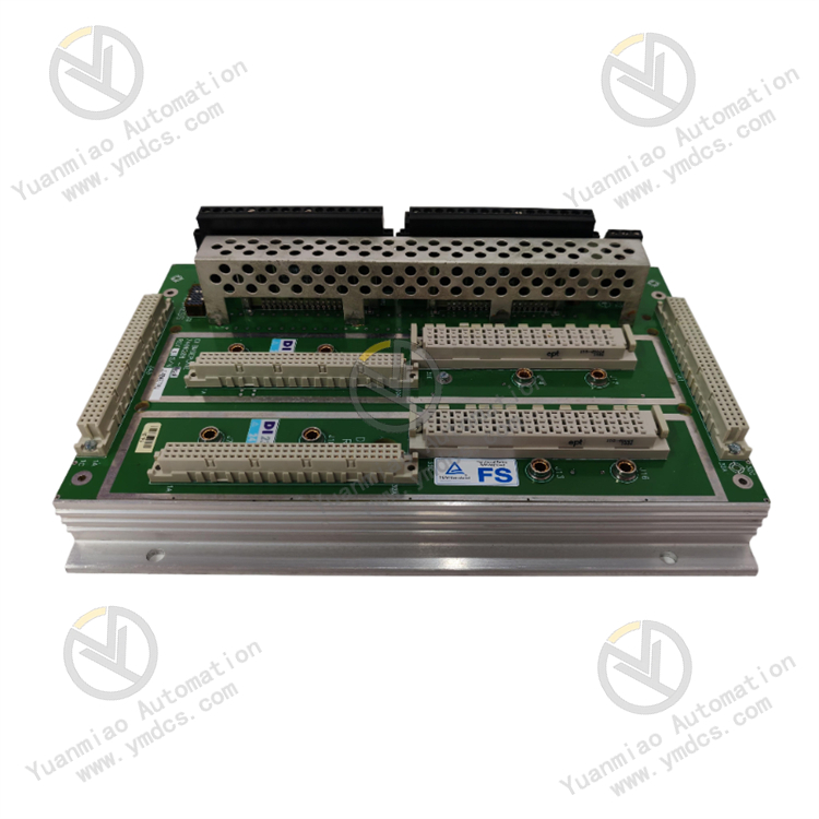
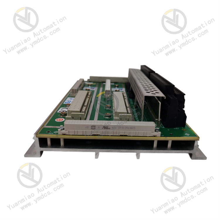
Description
The TRICONEX AI2361 is a high-performance analog input module specifically designed for Triconex Safety Instrumented Systems (SIS). It is used to collect and process analog signals (such as voltage, current, and temperature) in industrial automation scenarios. Its core functions include:
- Precise Signal Acquisition: Supports multiple analog input types to ensure high-precision measurement of critical process data in industrial environments.
- Safety Integration: Meets the high-reliability requirements of Triconex SIS, suitable for safety-critical applications (such as SIL 3-level systems).
- Harsh Environment Adaptability: Features anti-interference and vibration resistance, making it suitable for demanding industrial scenarios such as oil and gas, chemical, power, and pharmaceuticals.
Features
High Reliability and Safety
- Supports Triple Modular Redundancy (TMR) design, reducing single-point failure risks through hardware and software fault-tolerant mechanisms.
- Complies with functional safety standards such as IEC 61508/61511, suitable for SIL 3-level safety systems.
Multi-Type Signal Compatibility
- Supports various input signal types: 4-20mA current, 0-10V voltage, thermocouples (e.g., J/K/T types), resistance temperature detectors (RTDs, e.g., Pt100), etc.
- Built-in signal conditioning and isolation functions reduce the impact of external interference on measurement accuracy.
High Precision and Real-Time Performance
- High-resolution analog-to-digital conversion (typically 16 bits or higher) ensures accurate signal acquisition.
- Fast sampling rates meet real-time control and monitoring requirements.
Convenient Diagnosis and Maintenance
- Built-in online self-diagnosis functions for real-time monitoring of module status (e.g., channel faults, power anomalies) with alarms via LED indicators or system software.
- Supports hot-swapping for convenient online maintenance and replacement, minimizing downtime.
Industrial-Grade Design
- Wide operating temperature range (e.g., -40°C to +70°C) adapts to extreme environments.
- Resistant to vibration, shock, and electromagnetic interference (EMI/EMC), complying with industrial standards (e.g., IEEE 1158, ISA 12.12.01).
Technical Specifications (Taking 7400210-020 as an Example)
| Parameter | Description |
|---|---|
| Number of Input Channels | Typically 16 channels (subject to the model), supporting differential or single-ended input. |
| Signal Types | - Current: 4-20mA, 0-20mA - Voltage: 0-5V, 0-10V - RTD: 2/3/4-wire Pt100 - Thermocouples: J/K/T/E types, etc. |
| Resolution | 16 bits or higher, depending on the signal type. |
| Accuracy | Typical value ±0.1% F.S. (full scale), with slight variations for different signal types. |
| Sampling Rate | Configurable per channel, up to hundreds of samples per second. |
| Isolation Characteristics | Isolation voltage between channels ≥500V AC to prevent crosstalk and external interference. |
| Power Supply | Powered by the Triconex system backplane (typically 24V DC), with low power consumption (typical value <5W). |
| Communication Interface | Communicates with the controller via the Triconex backplane bus, supporting redundant communication links. |
| Mechanical Specifications | Complies with Triconex standard module dimensions, supporting rail mounting or rack mounting. |
Installation and Wiring Guide
Pre-Installation Preparation
- Hardware Preparation
- TRICONEX AI2361 module (7400210-020), installation rails or racks, screwdrivers, and other tools.
- Ensure the system backplane is powered and grounded, complying with electrical safety specifications (e.g., grounding resistance ≤1Ω).
- Environmental Requirements
- The installation location must be dry, well-ventilated, and away from strong electromagnetic sources (such as motors and transformers).
- The ambient temperature must be within the module's operating range (-40°C to +70°C), avoiding direct sunlight or condensation.
Module Installation Steps
- Fixing the Module
- Insert the module into the specified slot of the Triconex rack (ensure alignment with the backplane connector) and secure it with screws or clips.
- For redundant systems, install in redundant slots (e.g., Slot A and Slot B).
- Terminal Connection
- Select the corresponding terminal block (e.g., AI terminal block) based on the signal type and crimp the wires using specialized tools.
- Current signals: Connect the positive and negative wires of the 4-20mA signal to the "+" and "-" terminals of the corresponding channel, ensuring the loop is closed.
- Voltage signals: Directly connect the positive and negative terminals of the voltage source, paying attention to polarity.
- RTD/thermocouples: Connect to dedicated terminals according to the wiring type (e.g., 3-wire Pt100) to avoid measurement errors caused by wire resistance.
- Grounding: Connect the module's grounding terminal (GND) to the system's protective ground to ensure single-point grounding.
Precautions
- Disconnect the system power before wiring to avoid electric shock or module damage.
- Use independent cables for different signal types and avoid parallel routing with power cables to reduce electromagnetic interference.
- For thermocouple signals, use compensating cables and ensure correct cold junction temperature compensation.
Configuration and Commissioning Process
Software Tool Preparation
- Installing Configuration Software
- Use Triconex official software (such as TriStation) for module parameter setup and system configuration.
- Ensure the software version is compatible with the module's firmware, and download the latest drivers or firmware update packages from the official website.
Parameter Configuration Steps
- Module Identification
- Scan the hardware in TriStation to confirm that the AI2361 module is recognized by the system (displaying the module model and firmware version).
- Channel Configuration
- Set signal types (e.g., 4-20mA, Pt100), range limits (e.g., 0-100°C), filter time constants, etc., for each channel.
- Enable redundant channels (if required) and configure voting mechanisms between channels (e.g., two-out-of-three voting).
- Linearization and Calibration
- Enable built-in linearization algorithms or import custom curves for non-linear signals (such as thermocouples).
- Perform regular calibration (e.g., using high-precision signal sources) to ensure measurement accuracy, and archive calibration records.
- Alarm and Diagnosis Settings
- Define high and low alarm thresholds for channels and fault response strategies (such as triggering system shutdown or alarms).
- Enable module self-diagnosis functions (e.g., channel open/short circuit detection, power fault detection) and configure alarm output methods (such as LED indicators and system logs).
System Testing
- Signal Injection Test
- Input standard signals (e.g., 12mA corresponding to 50% range) into the module using a calibrator and check if the values displayed in the software match theoretical values (errors must be within allowable limits).
- Redundancy Switchover Test
- Simulate a main module failure (such as power loss) to verify whether the redundant module automatically takes over signal acquisition without data loss or jumps during the switchover.
- Safety Function Test
- Conduct functional safety tests integrated with the SIS to verify whether the module can correctly trigger safety actions (such as ESD shutdown) in fault scenarios.
Maintenance and Troubleshooting
Daily Maintenance
- Regularly check the status of module LEDs (such as power indicators, communication indicators, and channel fault lights) to ensure no abnormal alarms.
- Clean dust from the module surface to prevent overheating due to poor heat dissipation.
Common Faults and Solutions
| Fault Phenomenon | Possible Causes | Solutions |
|---|---|---|
| No power indication on module | Backplane power failure, loose connector | Check power voltage, reinsert the module, or replace the backplane slot |
| Abnormal channel data (jumps) | Signal interference, loose wiring, sensor failure | Check cable shielding and grounding, rewire, or calibrate the sensor |
| Communication interruption | Backplane bus failure, abnormal module firmware | Replace the redundant module, upgrade the firmware, or check the bus connector |
| Calibration error exceeding range | Expired calibration cycle, insufficient signal source accuracy | Recalibrate the module or use a higher-precision calibration device |

Firmware Upgrade
- Connect to the module via TriStation software, download and install the latest firmware. Ensure stable power during the upgrade to avoid module damage caused by power interruptions.
Application Scenarios
- Process Control: Temperature collection in chemical reactors, pipeline pressure monitoring, liquid level measurement, etc.
- Safety Systems: Analog signal input for emergency shutdown systems (ESD), such as current signals from flame detectors and toxic gas concentration monitoring.
- Energy Industry: Turbine vibration detection in power plants (with accelerometers), real-time monitoring of process parameters on oil platforms.
- Pharmaceuticals and Food: Temperature and humidity monitoring in clean rooms, pH value collection in fermentation tanks, meeting compliance requirements (e.g., FDA, GMP).