Description
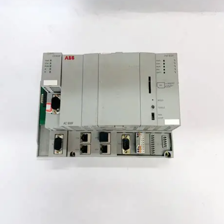
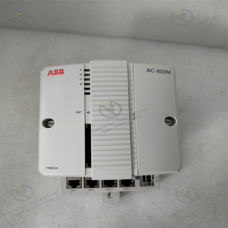
ABB PM856AK01 3BSE066490R1
Basic Positioning and Application Scenarios
The PM856AK01 is a high-performance industrial controller module launched by ABB, belonging to the AC 800M controller series. It is primarily used in fields such as process automation, manufacturing production lines, energy management, and building automation. Its design goal is to meet the real-time, reliability, and scalability requirements of complex control systems, support redundant configurations, and is suitable for industrial environments with extremely high stability requirements (such as chemical, power, and metallurgical industries).
Core Functional Features
1. High-Performance Processing Capability
- Processor: Equipped with a multi-core ARM Cortex-A9 processor running at a frequency of up to 1 GHz, it can quickly handle tasks such as logic control, data computation, and communication protocols, supporting complex algorithms and high-frequency real-time control.
- Data Processing Efficiency: Capable of real-time processing of large volumes of I/O signals, execution of high-speed closed-loop control (e.g., PID regulation), and support for multi-task parallel operation to meet millisecond-level control cycle requirements.
2. Redundancy and High Reliability Design
- CPU Redundancy Support: Can form a redundant pair (master-backup mode) with another PM856AK01, synchronizing data through a redundant communication bus (such as CEX-Bus). In the event of a master controller failure, the backup controller can switch over in milliseconds to ensure uninterrupted system operation.
- Hardware Reliability: Uses industrial-grade components, supports wide-temperature operation (-20°C to +60°C), and is resistant to vibration, shock, and electromagnetic interference, complying with industrial standards such as IEC 61131-2.
3. Rich Communication Interfaces
- Ethernet Ports: Equipped with 2 × 10/100/1000 Mbit/s adaptive Ethernet interfaces (RJ45), supporting industrial Ethernet protocols (such as PROFINET, EtherNet/IP, Modbus TCP), which can connect to host computers, SCADA systems, or other intelligent devices.
- Serial Ports: Provides 2 × RS-232/485 serial ports, supporting protocols such as Modbus RTU and ASCII for connecting sensors, instruments, or third-party devices.
- Expansion Bus: Connects expansion modules (such as I/O modules and communication interface modules) through the CEX-Bus (Communication Expansion Bus), supporting up to 7 S800 I/O unit clusters, with each cluster expandable to 12 I/O modules.
4. Data Storage and Real-Time Clock
- Memory Configuration: Built-in 2 GB DDR3 RAM (for program operation and data caching) and 8 GB eMMC flash memory (for storing programs, configuration files, and historical data), supporting data retention during power outages.
- Real-Time Clock (RTC): Built-in battery-backed real-time clock ensures system time accuracy and supports event log timestamps and timed task triggering.
5. Modular Expansion and Flexible Configuration
- Support for Multiple I/O Modules: Can connect to ABB S800 series I/O modules (such as digital, analog, temperature measurement, pulse counting, etc.), achieving plug-and-play via the bus.
- Software Compatibility: Programmed using ABB AC 800M engineering software (such as Control Builder M), supporting IEC 61131-3 standard programming languages (LD, FBD, ST, SFC, etc.), facilitating logic development and system debugging for users.
6. Status Monitoring and Maintenance
- LED Indicators: Equipped with multiple sets of status indicators (power, operation, communication, fault, redundancy status, etc.), which visually display the module's working status for quick fault location.
- Firmware Upgrade: Supports remote firmware upgrades via Ethernet without hardware disassembly, reducing maintenance costs.
Technical Parameters
| Parameter Category | Specific Indicators |
|---|---|
| Processor | Multi-core ARM Cortex-A9, 1 GHz |
| Memory | 2 GB DDR3 RAM, 8 GB eMMC flash memory |
| Communication Interfaces | - 2 × 10/100/1000 Mbit/s Ethernet (RJ45) - 2 × RS-232/485 serial ports |
| Power Supply | DC 24V (range: 19.2–30V DC), reverse polarity protection, power consumption ≤15W (typical) |
| Dimensions | Width × Height × Depth: 245mm × 105mm × 280mm (DIN rail mounting) |
| Weight | Approximately 2.1 kg |
| Protection Level | IP20 (protection against solid foreign objects) |
| Operating Temperature | -20°C to +60°C (natural cooling without a cooling fan) |
| Redundancy Support | CPU redundancy, power redundancy, communication bus redundancy |
| Certifications | CE, ATEX (optional for explosion-proof environments), IEC 61131-2, etc. |
Application Scenarios
- Process Control: Chemical reactor control, refinery distillation systems, pharmaceutical industry mixing and stirring control, etc.
- Power Automation: Substation monitoring, photovoltaic inverter cluster control, energy storage system management.
- Manufacturing: Automotive production line robot collaborative control, food packaging equipment automation, semiconductor wafer processing equipment.
- Building and Energy Management: Smart building HVAC systems, cold and heat source linkage control, energy metering, and optimization scheduling.
Differences from Previous Products (e.g., PM891K01)
- Performance Improvement: The PM856AK01 uses a more advanced ARM multi-core processor, with significantly superior computing speed and multi-task processing capabilities compared to the PM891K01's PowerQUICC III single-core processor.
- Memory Expansion: Memory capacity has been upgraded from 256MB RAM in the PM891K01 to 2GB RAM, and flash memory has been expanded from 512MB to 8GB, supporting larger-scale program and data storage.
- Communication Upgrade: Ethernet ports have been upgraded to gigabit speeds, compatible with more industrial Ethernet protocols to meet high-speed data interaction requirements.
- Energy Efficiency Optimization: Lower power consumption and a wider operating temperature range, adapting to harsher industrial environments.

Common Faults and Solutions for ABB PM856AK01 (3BSE066490R1) Controller
I. Power Supply Faults
Fault Symptoms
- Power indicator (e.g., PWR LED) is off or flashing abnormally.
- The module is unresponsive, unable to start, or frequently reboots.
Possible Causes
- External Power Supply Abnormality: Input voltage exceeds the allowable range (e.g., DC 24V module voltage below 19.2V or above 30V), power interruption, or excessive ripple.
- Power Connection Issues: Loose terminals, damaged cables, or poor contact.
- Internal Power Supply Faults: Damaged power module, aged capacitors, or circuit short circuits.
Solutions
- Check External Power Supply:
- Measure the input voltage with a multimeter to ensure it is within the nominal range (e.g., verify 19.2–30V DC for a DC 24V module).
- Inspect the power adapter, switching power supply, or power supply circuit to eliminate power outages, voltage fluctuations, or ripple interference (ripple should be ≤5%).
- Investigate Connection Cables:
- Re-plug the power terminals to ensure secure connections, free from oxidation or corrosion; replace damaged cables.
- Replace Power Module or Return for Repair:
- If the external power supply is confirmed to be normal but the module still has no power, it may be an internal power supply fault, requiring contact with ABB after-sales service for module replacement or repair.
II. Communication Faults
Fault Symptoms
- Failure to communicate with host computers (e.g., engineer stations), PLCs, or other devices.
- Communication indicator lights (e.g., LINK/ACT LED) are off or flashing abnormally.
- Data transmission interruptions, packet loss, or high error rates.
Possible Causes
- Communication Parameter Errors: IP address conflicts, inconsistent port numbers, baud rates, protocols (e.g., Modbus, Profinet), or parity bit settings.
- Physical Connection Issues: Damaged network/serial cables, loose interfaces, poor crystal head contact, or switch failures.
- Electromagnetic Interference: Communication cables are close to high-power equipment, causing signal attenuation or bit errors.
- Module Hardware Faults: Damaged communication chips, burnt interfaces, or firmware anomalies.
Solutions
- Verify Communication Parameters:
- Ensure the device IP address matches the network segment (e.g., the default IP of the controller is 192.168.1.101, which needs to be in the same subnet as the computer's IP).
- Check that communication protocols, baud rates, slave addresses, etc., in the configuration software (e.g., ABB Control Builder M) match those of the peer device.
- Investigate Physical Connections:
- Use a network cable tester to detect cable continuity and replace faulty cables; re-plug interfaces or replace switch ports.
- For serial communication (e.g., RS-485), check whether the terminal wiring is correct (e.g., A/B wires reversed).
- Eliminate Interference Sources:
- Lay communication cables separately from high-power lines, use shielded cables, and ensure reliable grounding.
- Update Firmware or Replace Module:
- If parameters and connections are both normal, attempt to update the controller's firmware to the latest version via the configuration software.
- If the firmware update is ineffective, it may be a hardware fault, requiring replacement of the communication module or the entire unit for repair.

III. Processor/System Faults
Fault Symptoms
- Abnormal controller operation indicators (e.g., RUN LED) (constant on, off, or too fast flashing).
- System crashes, interrupted program execution, or abnormal logic control.
- Redundancy switchover failure or inconsistent status between master and backup controllers.
Possible Causes
- Overheating or Poor Heat Dissipation: The installation environment temperature exceeds the allowable range (e.g., -10°C to 55°C), and blocked ventilation holes cause processor overheating.
- Memory or Storage Faults: RAM errors, damaged flash cards, or lost program files.
- Firmware/Program Issues: Program logic errors, infinite loops, incompatible firmware versions, or corrupted file systems.
- Redundancy Configuration Errors: Incorrect redundancy parameter settings, communication link failures between master and backup controllers (e.g., CEX bus anomalies).
Solutions
- Improve Heat Dissipation Environment:
- Ensure the module is installed in a well-ventilated location, away from heat sources, with normal cabinet fan operation.
- Clean dust from the module surface and inside the cabinet to prevent ventilation holes from being blocked.
- Check Memory and Storage:
- Restart the controller and attempt to restore default configurations or re-download programs.
- If using an external flash card, check if the card is securely inserted or damaged; try formatting it (back up data in advance) or replace it with a new card.
- Repair Programs or Firmware:
- Use configuration software to check program logic and eliminate infinite loops or syntax errors; monitor variable statuses via online diagnostic tools.
- If the firmware is abnormal, re-flash the firmware via safe mode (e.g., Bootloader) (operate with reference to the official manual).
- Redundancy System Investigation:
- Check the connection of redundancy communication cables (e.g., CEX bus) for tightness and replace faulty cables or interface modules.
- Confirm that redundancy parameter settings are correct (e.g., master-backup roles, switchover delays), and re-initialize the redundancy pair if necessary.

IV. I/O Communication Faults
Fault Symptoms
- Inability to recognize expanded I/O modules (e.g., S800 I/O units).
- Abnormal I/O module indicator lights (e.g., ERR LED on), incorrect or unresponsive input/output values.
Possible Causes
- Backplane Bus Connection Issues: Loose, damaged, or poorly connected CEX bus or I/O bus cables.
- Module Address Conflicts: Physical addresses of I/O modules (e.g., DIP switches) are inconsistent with addresses in the configuration software.
- Power Supply Abnormalities: I/O module power not connected or insufficient voltage.
- Module Hardware Damage: Internal circuit failures or burnt interfaces in I/O modules.
Solutions
- Check Bus Connections:
- Re-plug CEX bus cables or I/O bus modules to ensure tight connections; replace faulty cables.
- Verify Module Addresses:
- Check the address DIP switches of I/O modules against the hardware manual to ensure consistency with settings in the configuration software (e.g., slave addresses 1–127).
- Ensure Normal Power Supply:
- Measure the power input of I/O modules to ensure voltage meets requirements (e.g., DC 24V), and replace faulty power modules.
- Replace Module Testing:
- Swap the faulty module with a normal one. If the problem transfers to another module, the original module may have a hardware fault and needs replacement.
V. Abnormal LED Indicator Lights
Faults can be quickly located by observing the LED status on the controller panel. The meanings of common indicators and handling suggestions are as follows:
| Indicator | Normal Status | Abnormal Status and Possible Causes | Solutions |
|---|---|---|---|
| PWR (Power) | Constant on (green) | Off: Power not connected or internal fault Blinking: Unstable voltage | Check power input, replace module |
| RUN (Operation) | Periodic flashing (green) | Off: System not started Constant on: System crash or program anomaly | Restart module, check program or firmware |
| COM (Communication) | Flashing (green) | Off: Communication interrupted Rapid flashing: Abnormal data transmission | Check communication cables, parameters, or peer devices |
| ERR (Error) | Off | Constant on (red): Hardware fault or configuration error | View diagnostic logs, contact technical support |
| RED (Redundancy) | Master: Constant on Backup: Off | Both master and backup off: Redundancy link fault Both constant on: Competition conflict | Check redundancy cables, reconfigure redundancy |