Description
1. Product Overview
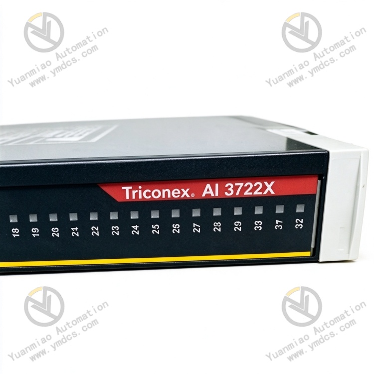
Triconex 3722X is a TMR Digital Input Module (DI) developed by Triconex, now part of Schneider Electric Triconex safety‑system product portfolio. Belonging to the Triconex TMR safety‑system 3700‑series I/O hardware product line, it is widely deployed alongside Triconex Trident / Tricon series TMR safety‑PLC systems, and serves as the core I/O hardware for field digital‑signal acquisition within SIS/ESD safety systems.
Designed for SIS/ESD/BMS/F&G systems in petrochemical, nuclear‑power, long‑distance oil‑gas transmission, LNG, offshore platform, metallurgical and power‑generation industries, it is critical hardware for connecting field digital measurement points of safety‑instrumented systems to TMR safety controllers. Under Triconex TMR architecture, one single 3722X digital input module integrates three independent internal acquisition circuits. Three channels sample the same field signal and perform 2‑out‑of‑3 voting over the backplane. Failures of single‑point components or single‑loop faults will not result in misjudgement of acquisition results. It ranks among the most reliable digital‑input hardware for global SIS/ESD applications.
It has passed a full set of industrial‑grade and functional‑safety‑oriented tests including full‑load burn‑in, thermal cycling, vibration‑shock testing, dielectric‑withstand testing, electromagnetic‑interference evaluation and channel‑fault‑injection testing. Supporting 7×24‑hour year‑round continuous full‑load operation, it withstands harsh cabinet‑level conditions such as elevated enclosed‑space temperature, dust‑humidity exposure, thermal cycling, strong electromagnetic interference and mains‑voltage fluctuations.
2. Functional Features
2.1 TMR 3‑Channel Redundant Internal Acquisition with High‑SIL4 Safety Rating
The 3722X digital input module integrates three independent signal‑acquisition circuits internally. Each channel performs galvanic isolation, level detection and filter shaping for the identical field digital‑contact signal. Acquisition results from three channels are sent to main processors after 2‑out‑of‑3 (2oo3) voting over the backplane. Failure of any single acquisition‑circuit component, optocoupler or filter element leaves the other two channels capable of correctly sampling field signals without misjudgement of field status. This module‑level TMR redundancy eliminates single‑point‑failure risks at the I/O source. Together with TMR main processors and TMR communication modules, it forms a complete triple‑modular‑redundant safety architecture achieving IEC 61508 SIL4 safety‑integrity level.
2.2 Centralised Connection for Multi‑Channel Digital Contacts with Standardised Loop Layout
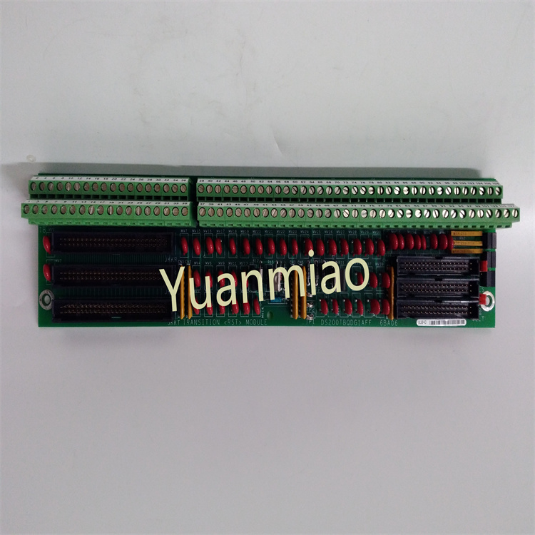
Equipped with multiple sets of standard industrial terminal blocks, the module centrally receives field safety‑related digital signals: proximity switches, pressure switches, temperature switches, push‑buttons, relay auxiliary contacts, solenoid‑valve position feedback, safety interlock contacts, flame‑detector contacts, fire‑and‑gas detector contacts and more. Layout strictly follows original Triconex point‑definition specifications with clear signal zoning, separation of strong‑ and weak‑current circuits and unambiguous wiring markings. It eliminates traditional‑loop‑pain points such as messy wiring, confused measurement points and cross‑loop interference, enabling standardised and efficient field cabling, loop verification and troubleshooting, perfectly matching standardized turn‑key construction and safety‑operation‑maintenance management for SIS/ESD systems.
2.3 Galvanic Isolation and Surge Protection for High Noise Immunity
Each digital‑input channel is fitted with built‑in optocoupler isolation circuits, providing complete galvanic isolation between field loops and TMR backplane / CPU circuits. It effectively blocks ground‑loop currents, common‑mode interference and surge voltages from penetrating into safety control systems. Each channel integrates overcurrent protection, surge suppression, varistors, RC filtering and ESD protection mechanisms to counteract transient field‑line surges, solenoid‑valve coil switching transients, VFD harmonics and lightning‑induced transients in complex industrial electromagnetic environments. It prevents damage to safety main‑control hardware and field‑side equipment caused by strong‑crosstalk or abnormal‑power surges, and avoids whole‑module failure or safety‑system anomalies triggered by propagation of single‑loop faults.
2.4 Channel‑Level Short‑Circuit / Open‑Circuit Detection for Precise Fault Localisation
Built‑in channel‑level field‑loop diagnostic circuits continuously monitor short‑circuit, open‑circuit, over‑voltage, under‑voltage and poor‑contact conditions for every input channel. Via TriStation 1131 engineering software, maintenance personnel can remotely retrieve per‑channel diagnostic words, loop health status and fault types to accurately locate faulty channels and root causes (damaged field contacts, broken cables, short‑circuited wiring, loose terminals, etc.). Field‑side manual measurement for every channel is avoided, greatly shortening troubleshooting and repair turnaround times for safety systems.
2.5 On‑Board Self‑Diagnostics and Status Indicators for Efficient Operation‑Maintenance
Multi‑layer self‑diagnostics monitor three‑channel acquisition circuits, backplane communication, power‑supply units and isolation circuits. Multiple front‑panel LEDs provide real‑time indication of power‑supply health, run status, channel status and fault alarms. The module supports online hot‑swap: a faulty 3722X may be removed and replaced without system shutdown. After power‑up, the replacement unit automatically synchronises configuration parameters from the corresponding main processor and seamlessly restores channel‑acquisition functions. Form‑factor, connector pin‑out and front‑panel layout are compatible with other I/O modules within Triconex 3700‑series, delivering good spare‑part commonality.
2.6 Industrial‑Grade High Noise Immunity and Stable Wide‑Temperature Operation
Built upon Triconex industrial‑hardened electrical architecture with multi‑layer electromagnetic shielding, the module exhibits excellent EMC performance. Its operating‑temperature range covers typical industrial‑cabinet conditions. Tolerant of high‑temperature, low‑temperature, high‑humidity and ageing‑prone environments, it sustains long‑term operation under harsh cabinet conditions including high enclosed‑space temperature, dust‑humidity exposure, thermal cycling and continuous vibration, without false channel diagnostics, acquisition drift or abnormal TMR voting, ensuring year‑round stable online performance of safety systems.
2.7 Native Triconex‑System Compatibility for Plug‑and‑Play Deployment
Natively compatible with backplane architecture of Triconex Trident / Tricon TMR systems. Point definitions, signal protocols, mechanical dimensions and connector pin‑outs fully comply with original‑system specifications. No extra adaptor modules, secondary‑signal conditioning or complex parameter calibration are required, supporting direct in‑situ installation for both legacy and modern Triconex systems. It seamlessly interfaces with peer main processors, communication modules, upper‑level engineering workstations and SCADA/DCS systems to realise real‑time digital‑signal upload, safety‑logic execution, interlock linkage and status monitoring.
3. Technical Specifications
3.1 Core Compatibility Parameters
| Item | Specification |
|---|---|
| Full Part Number | 3722X |
| Brand | Triconex (Schneider Electric) |
| Product Family | Triconex 3700 series / TMR Digital Input Module |
| Module Type | TMR Digital Input Module (DI) |
| Redundancy Architecture | Three independent internal acquisition channels per module; 2‑out‑of‑3 voting; single‑component fault does not corrupt acquisition results |
| Supported Systems | Triconex Trident / Tricon TMR safety‑PLC; SIS/ESD/BMS/F&G systems |
| Associated Hardware | Triconex rack backplane, main‑processor modules (MP3101S2), communication modules (3009X EICM), power‑supply modules |
| Core Functions | Field digital‑contact‑signal acquisition, galvanic isolation, 3‑channel TMR acquisition & voting, channel self‑diagnostics, backplane communication |
| Typical Applications | Petrochemical SIS/ESD interlocks, nuclear‑power protection, offshore platforms, LNG, BMS burner‑management, digital‑point‑connection for F&G fire‑and‑gas systems |
3.2 Electrical‑Performance Parameters
| Item | Specification |
|---|---|
| Signal Type | Field digital‑contact‑signal input (dry‑contact / wet‑contact); multi‑voltage‑level compatibility |
| Isolation Method | Independent optocoupler isolation per channel; complete galvanic separation between field loops and TMR backplane circuits |
| Protection Features | Built‑in overcurrent, surge‑suppression, varistor, RC‑filter and ESD protection; withstands transient abnormal‑voltage surges on field wiring |
| Safety Features | Channel‑level short‑/open‑circuit detection; 3‑channel TMR 2oo3 voting; single‑component fault does not corrupt acquisition results |
| Interface Configuration | Industrial screw‑type gold‑plated anti‑corrosion terminal blocks; backplane connectors for communication with TMR main processors |
| Acquisition Accuracy | Optocoupler isolation plus RC‑filter shaping; negligible‑signal distortion and false diagnostics over long‑distance wiring |
| Self‑Diagnostics | Multi‑layer channel‑level & board‑level diagnostics; fault‑LED indication and remote diagnostic‑word upload |
| Power Supply | Powered by Triconex rack redundant backplane power supplies; wide‑input‑voltage range |
| Electrical Stability | 7×24‑hour continuous operation; free of channel dropout, acquisition misjudgement and abnormal TMR voting |
3.3 Environmental and Mechanical Parameters
| Item | Specification |
|---|---|
| Operating Temperature | Industrial wide‑temperature cabinet‑grade design for enclosed‑cabinet service conditions |
| Storage Temperature | Qualified for extreme‑temperature storage and transportation |
| Operating Humidity | 5 %‑95 %RH (non‑condensing); tolerant of dusty high‑humidity cabinet environments |
| Environmental Resistance | Dust‑proof, moisture‑resistant, oil‑tolerant, thermal‑ageing‑resistant, vibration‑resistant, high‑EMI‑immunity |
| Mounting Method | Plug‑in installation onto Triconex TMR standard racks; online hot‑swap supported |
| Mechanical Construction | Industrial flame‑retardant reinforced PCB, metal front panel; anti‑vibration, anti‑loosening, wear‑resistant, ageing‑resistant, flame‑retardant and moisture‑resistant |
4. Hardware Configuration and Structural Advantages
4.1 Core Hardware Configuration
The 3722X digital input module adopts proven Triconex TMR‑system I/O hardware architecture. Key components include multi‑channel signal terminal blocks, three‑channel independent optocoupler‑based acquisition circuits, RC‑filter and level‑shaping units, channel‑level short‑/open‑circuit detection circuits, surge‑overcurrent‑protection loops, backplane‑communication connectors and stabilised‑power‑supply adaptation units. The three internal acquisition circuits are fully independent: each incorporates dedicated optocouplers, current‑limiting resistors, filter components and detection circuits. Three channels sample the same field signal in parallel and deliver final values to main processors after backplane‑based 2‑out‑of‑3 voting. This module‑level TMR‑redundancy design eliminates single‑component‑failure risks at I/O board level.
The rear‑side gold‑plated Triconex‑TMR‑standard backplane connector ensures reliable mating with rack backplanes. The front panel hosts screw‑type field‑wiring terminal blocks and multi‑group status‑LED arrays. Signal definitions strictly match original‑manufacturer drawings to facilitate field construction and maintenance. The main PCB features industrial flame‑retardant reinforced construction. All components pass industrial‑temperature‑grade screening and full‑load‑burn‑in testing, optimised for long‑term unattended petrochemical‑cabinet operation, strong electromagnetic interference and thermal‑cycling environments.
4.2 Structural and Engineering‑Related Advantages
The module implements Triconex TMR‑standard modular rack mechanics. It is inserted directly into rack I/O slots and communicates with main processors via backplane, requiring no extra configuration or programming for plug‑and‑play operation. Dedicated TriStation 1131 engineering software unifies channel configuration, point‑list mapping, online monitoring and fault‑recording analysis. All channel‑configuration parameters and point‑list mappings can be backed‑up and archived online. After replacement of a faulty 3722X, the new unit automatically synchronises configurations without manual re‑commissioning.
Standardised hardware‑and‑software architecture lowers training overhead and spare‑part diversity for maintenance staff. For legacy Triconex TMR installations that have been in service for years, spare‑part availability and fault‑replacement capability of the 3722X digital input module directly determine reliable continuous acquisition of field digital measurement points within SIS/ESD systems. It constitutes a key strategic spare part for long‑term maintenance within high‑risk industries such as petrochemicals, nuclear power and offshore platforms.
5. Operating Principle
As field‑digital‑signal‑acquisition hardware for Triconex TMR systems, the 3722X digital input module implements a closed‑loop signal‑acquisition workflow: field‑contact‑signal reception → galvanic isolation & surge protection → three‑channel independent acquisition & filter shaping → 2‑out‑of‑3 voting → backplane upload to main processors → self‑diagnostics and fault tolerance. This workflow enables safe, reliable and accurate acquisition of field digital signals for SIS/ESD systems.
During operation, various field digital‑contact signals (proximity switches, pressure switches, temperature switches, push‑buttons, relay contacts, solenoid‑valve feedback, safety interlock contacts, etc.) are connected to corresponding terminal loops of the module. Incoming signals pass first through optocoupler‑isolation circuits to achieve physical galvanic separation between field loops and TMR backplane / CPU circuits, thoroughly mitigating field‑side strong‑crosstalk, ground‑loop currents and surge voltages. Meanwhile, built‑in overcurrent, surge‑suppression, varistor and RC‑filter‑protection circuits defend against transient field‑line anomalies.
Isolated and conditioned signals are fed simultaneously into three independent internal acquisition circuits. Each circuit performs level detection, filter shaping and threshold judgement to produce three separate acquisition results. Results are compared via TMR 2‑out‑of‑3 voting over the backplane: when two out of three values agree, that value is adopted as the final channel‑acquisition result and uploaded to main processors. If component failure distorts output from one acquisition channel, correct voting output is still guaranteed by the remaining two channels for valid field‑status delivery to main processors.
Voted channel‑acquisition values are transmitted to corresponding main processors over the backplane bus. Under scheduling of safety operating systems, main processors execute safety‑logic operations (interlock evaluation, ESD‑condition checking, protection‑action‑condition evaluation, etc.). Meanwhile, the module uploads channel status and diagnostic information (short‑circuit / open‑circuit / normal) to main processors and upper‑level engineering‑workstation / SCADA systems for operator supervision. Continuous on‑board self‑diagnostics monitor health status of three‑channel acquisition circuits, backplane communication and power‑supply circuits. Alarms are triggered via front‑panel LEDs and remote diagnostic‑word reporting upon anomaly detection. Maintenance personnel may hot‑swap faulty modules online. After power‑up, the replacement module automatically synchronises configurations and restores acquisition functions.
6. Troubleshooting
6.1 Abnormal Channel Status, False Diagnostics or Inconsistent Read‑backs
| Probable Cause | Diagnostic Approach | Remedial Action |
|---|---|---|
| Damaged field safety contacts, broken or short‑circuited field wiring | Review channel diagnostic words within TriStation; perform field continuity measurement of loops | Replace faulty field contacts / switches; repair broken / short‑circuited cables |
| Loose, oxidised or poorly‑mated field‑side terminals | Observe channel‑status trends; inspect terminal crimping quality on‑site | Retighten terminals; clean or replace oxidised terminals; re‑crimp cable lugs |
| Faulty channel‑isolation / acquisition circuitry inside module | Inject standard test‑signal or short‑circuit module input terminals; observe channel‑status behaviour | Perform compliant online hot‑swap replacement of 3722X module; restore channel configuration |
| Field‑site electromagnetic interference inducing false channel diagnostics | Observe whether faults coincide with start‑stop cycles of frequency converters or large motors | Check cable‑shield‑earthing practice; route signal cables separately from power cables |
6.2 All Module Channels Abnormal or Backplane‑Communication Loss
| Probable Cause | Diagnostic Approach | Remedial Action |
|---|---|---|
| Loose, oxidised or retracted pins on backplane connector | Remove module completely; inspect gold‑plated fingers and backplane pins | Clean gold‑plated fingers and pins; re‑insert and latch module securely; repair backplane for retracted pins |
| Fault of peer main processor or backplane communication | Inspect main‑processor LED status and system alarms; cross‑reference with modules in adjacent slots | Troubleshoot main processor and backplane per procedures; no modification required for this I/O module |
| Abnormal cabinet power supply or faulty power‑supply module | Measure backplane supply voltage against nominal specifications | Troubleshoot cabinet power loops; replace faulty power‑supply module; module recovers automatically |
6.3 Safety‑Interlock False Trip or Failure to Trip upon Protection Demand
| Probable Cause | Diagnostic Approach | Remedial Action |
|---|---|---|
| Erroneous safety‑logic configuration or mis‑downloaded interlock logic | Monitor safety‑logic‑block and input‑variable status online; cross‑validate against design logic | Restore last controlled‑version logic; re‑deploy logic following MOC procedures |
| Poor‑contact safety contacts leading to interlock misjudgement | Measure loop resistance and contact‑contact‑resistance of interlock loops | Clean or replace safety contacts; mitigate excessive loop‑contact resistance |
| Fault of output‑module drive‑loops or solenoid‑valve sticking | Review output‑channel status; inspect solenoid valves / actuators locally | Repair output modules; replace faulty solenoid valves / actuators |