Description
1. Product Overview
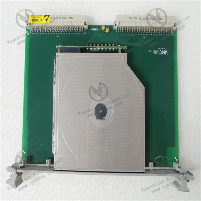
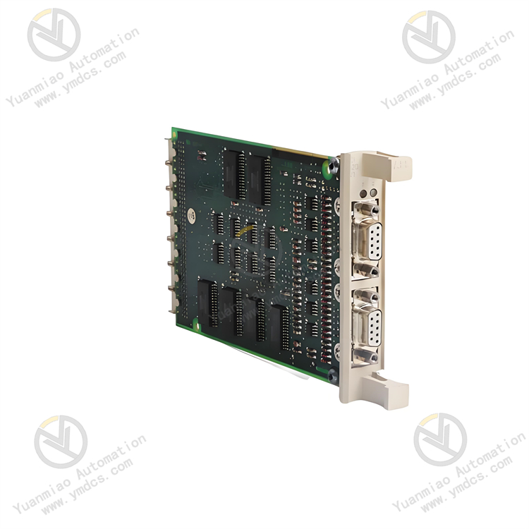
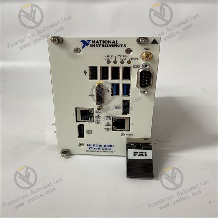
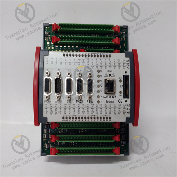
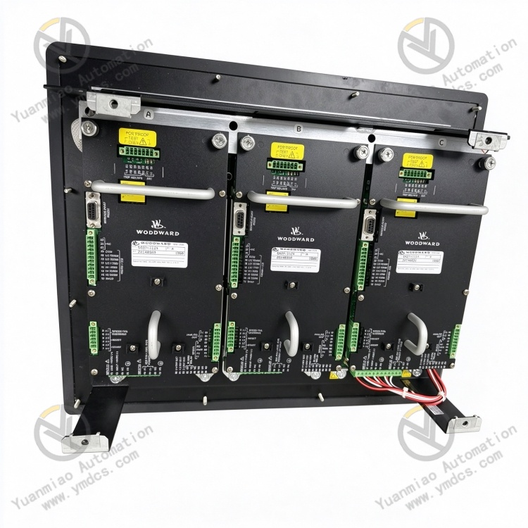
Woodward 5437‑1124 is a dedicated control module within the industrial turbine and engine control‑system product line of Woodward, Inc. Belonging to the Woodward 5437 series industrial control hardware, it is widely deployed in Woodward MicroNet, ProNet, Digital Control and other turbine/engine control systems, and constitutes a core component for control systems of gas turbines, steam turbines, hydro‑turbines, diesel engines, compressors and generator sets. Designed for turbine unit and reciprocating‑engine control applications in power plants, petrochemical facilities, long‑distance pipelines, industrial drives and marine propulsion sectors, the module undertakes tasks including field‑signal acquisition, control‑logic computation, actuator drive, communication interfacing and power‑supply management. It serves as a critical interconnecting hardware between field loops and the main control system of Woodward control systems.
It has undergone a full suite of industrial‑grade tests including full‑load burn‑in, thermal cycling, vibration‑shock testing, dielectric‑withstand evaluation and electromagnetic‑interference testing. Supporting 7×24‑hour year‑round continuous full‑load operation, it withstands harsh cabinet‑level conditions such as elevated enclosed‑space temperature, dust‑humidity exposure, thermal cycling, strong electromagnetic interference and mains‑voltage fluctuations. Given the large global installed base of Woodward turbine and generator‑set control systems, 5437‑series modules represent critical hardware assets. Spare‑part availability, fault‑replacement capability and system maintenance are essential for safe operation of in‑service units, and these modules are key hardware for control‑system retrofits and strategic spare‑part inventory.
2. Functional Features
2.1 Centralised Multi‑Channel Signal Access for Standardised Loop Organisation
As a dedicated control module for Woodward industrial control systems, Woodward 5437‑1124 integrates multiple standard industrial wiring terminals for centralised reception of field‑process signals including analogue signals, discrete contact signals, speed signals, temperature signals, pressure signals and actuator‑feedback signals. It consolidates and categorises scattered field measurement points. Layout strictly follows Woodward original‑manufacturer point‑definition standards, featuring clear signal zoning, separation of high‑ and low‑voltage circuits and unambiguous wiring marking. It eliminates common‑pain‑points such as messy cabinet wiring, misidentified measurement points and cross‑loop interference, enabling standardised and efficient field cabling, loop verification and fault troubleshooting. It is well‑suited for standardized turn‑key construction and maintenance workflows for turbine‑ and engine‑control systems.
2.2 Electrical Isolation and Signal Conditioning for High Noise Immunity
The module incorporates optocoupler / electromagnetic isolation circuitry, signal‑filtering and level‑translation units to provide galvanic isolation between field loops and control‑system backplane / CPU circuits. It effectively blocks ground‑loop currents, common‑mode interference and surge‑voltage transients propagating into the main control system. Built‑in overcurrent, surge‑suppression, varistor and ESD‑protection mechanisms defend against line‑borne transient surges, electromagnetic radiation and variable‑frequency‑drive harmonic interference. It prevents damage to main controllers and front‑end equipment caused by high‑voltage crosstalk and power‑supply anomalies, avoids whole‑module failure or control‑system malfunctions triggered by single‑loop faults, and greatly improves field‑loop noise immunity and operational fault tolerance for harsh electromagnetic environments at turbine installations.
2.3 Native Woodward‑System Compatibility with Plug‑and‑Play Performance
Natively compatible with the backplane architecture of corresponding Woodward industrial control systems, the module’s pin‑out definitions, signal protocols, mechanical dimensions and connector assignments fully match original‑equipment design. No additional adapter modules, secondary‑signal‑conditioning hardware or complex parameter calibration are required. It supports direct drop‑in installation for both new‑generation and legacy Woodward systems. Seamless interoperation with peer CPU main‑boards, engineering workstations, HMI devices and plant DCS platforms enables real‑time signal upload, control‑logic execution, interlock‑linkage functions and status monitoring. It fits multiple scenarios including new‑unit turn‑key projects, legacy‑system retrofits and loop‑rework activities.
2.4 Highly‑Reliable Gold‑Plated Terminal Construction for Stable Long‑Term Contact
Industrial‑grade gold‑plated anti‑corrosion wiring terminals deliver anti‑oxidation, anti‑corrosion, anti‑loosening and repeated‑mating performance. Tolerant of high‑humidity, dusty, oily and vibration‑prone field conditions, they eliminate risks of signal dropout and status misjudgement caused by terminal oxidation, poor contact or loose connections. Terminals maintain secure clamping and stable contact resistance over service life without signal drift, open‑circuit events or contact bounce. This greatly reduces risks of spurious protection trips, unit load‑reduction events and unplanned outages induced by signal‑loop faults, and extends overall signal‑loop service life.
2.5 On‑Board Self‑Diagnostics and Status Indicators for Precise Fault Localisation
Multi‑layer self‑diagnostics cover CPU communication links, channel loops, power‑supply circuits and isolation hardware. Multiple front‑panel LEDs provide real‑time indication of power‑supply health, run status, channel status and fault conditions. Using dedicated Woodward engineering software (e.g. ToolKit, CWT), maintenance personnel can remotely retrieve diagnostic words, channel status registers and fault codes to pinpoint faulty channels and root‑causes without cabinet disassembly, shortening troubleshooting and repair turnaround times for production units.
2.6 Modular Zero‑Adjustment Design for Efficient Maintenance‑Driven Replacement
Adopting standard plug‑in mechanics for Woodward industrial‑control‑system racks, the module achieves accurate rack alignment, simple handling and secure latching, matching standard Woodward cabinet‑rack layouts. Standardised terminal interfaces and well‑defined signal‑loop assignments eliminate requirements for specialised commissioning, system‑logic rework or configuration modification. Non‑destructive drop‑in replacement of faulty legacy modules is supported without unit shutdown or extensive rewiring. Field‑signal‑loop rectification and hardware upgrades can be completed rapidly, lowering control‑system maintenance costs, repair complexity and production‑loss exposure from unit outages.
3. Technical Specifications
3.1 Core Compatibility Parameters
| Item | Specification |
|---|---|
| Full Part Number | 5437‑1124 |
| Brand | Woodward (United States) |
| Product Family | Woodward 5437‑series industrial control module |
| Module Type | Dedicated control module for industrial turbine / engine control systems |
| Supported Systems | Woodward MicroNet / ProNet / Digital Control turbine and engine control systems |
| Associated Hardware | Matching‑system rack backplane, CPU main‑board, power‑supply module, I/O board, communication board, actuator‑drive board |
| Supported Signals | Analogue signals, discrete contact signals, speed signals, temperature signals, pressure signals, actuator‑feedback signals |
| Core Functions | Centralised multi‑channel signal access, galvanic isolation, signal conditioning, terminal breakout, loop‑surge protection, data upload |
| Typical Applications | Signal‑loop hardware for control systems of gas turbines, steam turbines, hydro‑turbines, diesel engines, compressors and generator sets |
3.2 Electrical Performance Parameters
| Item | Specification |
|---|---|
| Signal Types | Mixed analogue / discrete‑signal reception; multi‑voltage‑level compatibility |
| Isolation Method | Optocoupler / electromagnetic isolation; galvanic separation between field loops and control‑system backplane circuits |
| Protection Features | Built‑in overcurrent, surge, varistor and ESD protection; withstands transient abnormal‑voltage line events |
| Signal Accuracy | Signal‑filtering‑based conditioning; negligible signal drift over long‑distance transmission |
| Interface Configuration | Industrial screw‑type gold‑plated anti‑corrosion wiring terminals; backplane connector for interconnection with system CPU board |
| Electrical Stability | 7×24‑hour continuous operation; free of loop open‑circuits, signal anomalies and terminal‑contact failures |
| Insulation Performance | Compliant high‑voltage dielectric‑withstand rating; effective isolation against field high‑voltage crosstalk and leakage risks |
| Noise Immunity | Multi‑layer electromagnetic‑shielding architecture; tolerant of complex industrial power‑frequency and high‑frequency interference |
3.3 Environmental and Mechanical Parameters
| Item | Specification |
|---|---|
| Operating Temperature | Industrial wide‑temperature cabinet‑grade design for enclosed‑cabinet service conditions |
| Storage Temperature | Qualified for extreme‑temperature storage and transportation |
| Operating Humidity | 5 %‑95 %RH (non‑condensing); tolerant of dusty high‑humidity cabinet environments |
| Environmental Resistance | Dust‑proof, moisture‑resistant, oil‑tolerant, thermal‑ageing‑resistant, vibration‑resistant, high‑EMI‑immunity |
| Mounting Method | Plug‑in installation onto matching‑system standard racks; accurate alignment and simple handling |
| Mechanical Construction | Industrial flame‑retardant reinforced PCB, metal housing; anti‑vibration, anti‑loosening, wear‑resistant, ageing‑resistant, flame‑retardant and moisture‑resistant |
4. Hardware Configuration and Structural Advantages
4.1 Core Hardware Configuration
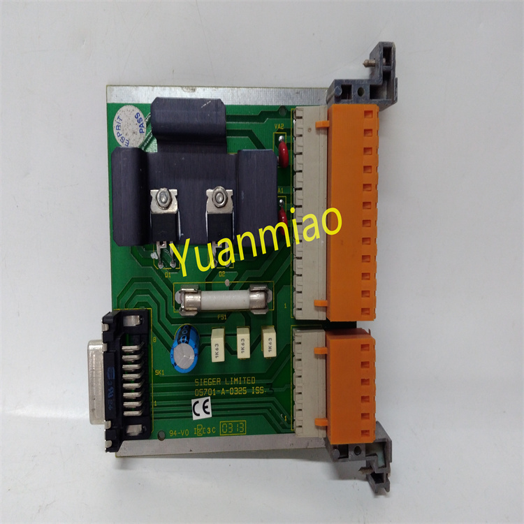
The 5437‑1124 module adopts dedicated Woodward industrial‑control‑module hardware architecture. Core components include multi‑channel‑signal wiring terminals, optocoupler / electromagnetic isolation circuitry, signal‑conditioning‑and‑filtering units, surge‑and‑overcurrent‑protection loops, backplane‑communication connectors and stabilised‑power‑supply adaptation units. Fine‑grained partitioned‑circuit design electrically separates field‑signal‑input loops, backplane‑communication loops and auxiliary‑power‑supply loops at hardware level to eliminate signal crosstalk and distortion. Key components and wiring terminals pass stringent original‑manufacturer screening including full‑load burn‑in, thermal shock, vibration‑fatigue, high‑voltage‑insulation and electromagnetic‑interference testing. Optimised for long‑term unattended turbine‑unit operation, complex‑field‑wiring scenarios and harsh cabinet conditions, the module reliably implements the full workflow of field‑signal reception, isolation, conditioning and breakout.
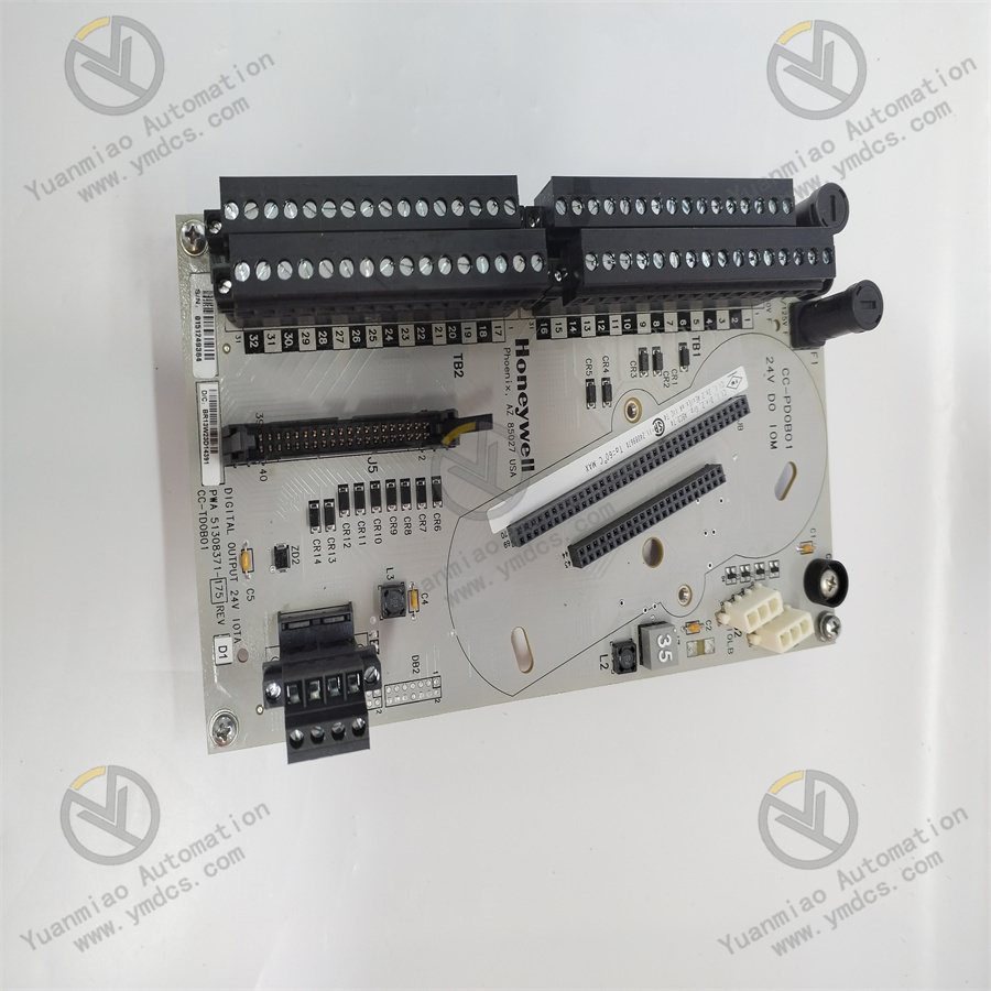
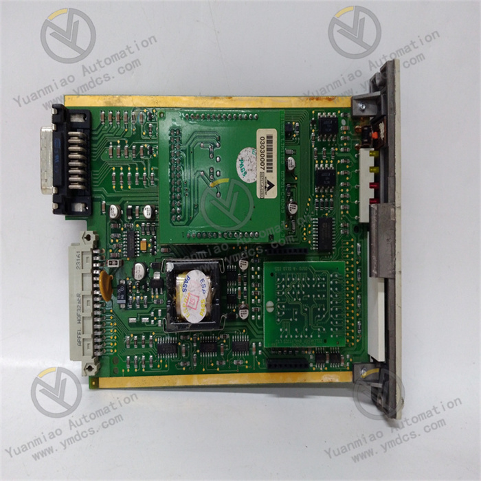
The rear‑side gold‑plated backplane connector provides robust mating with peer CPU main‑boards. The front‑panel accommodates screw‑type field‑terminal blocks and status‑LED arrays, with signal assignments fully aligned with original‑manufacturer drawings to facilitate on‑site commissioning and maintenance. The main PCB features industrial flame‑retardant reinforced construction; internal circuits receive multi‑point mechanical locking to resist long‑term cabinet vibration, thermal cycling, oil contamination and dust exposure, mitigating risks of hardware bad‑contacts, terminal loosening, module deformation and ageing‑related failures.
4.2 Structural and Engineering‑Related Advantages
The module implements Woodward‑standard compact modular mechanics, optimised for high‑density cabinet‑mount layouts with high space‑utilisation efficiency, secure installation and broad compatibility. Constructed from industrial flame‑retardant, moisture‑resistant and vibration‑hardened materials, it features multi‑point fixation for internal circuits and terminal bases to withstand sustained cabinet vibration, thermal cycling, humidity and dust. Clearly marked and well‑partitioned terminal pin‑outs reduce wiring‑error risks and simplify loop troubleshooting.
Drop‑in non‑destructive replacement of faulty legacy units is supported without rack modification, main‑control‑logic re‑configuration or unit shutdown, greatly lowering costs for control‑system retrofits, maintenance and emergency repairs. Standardised mechanical form‑factor is shared with other Woodward‑series control modules in terms of physical dimensions, terminal layout, mounting mechanics and commissioning software. This delivers high consistency for spare‑part management, personnel training and on‑site troubleshooting, fully meeting reliability requirements for long‑term stable operation of turbine‑ and engine‑control‑system signal loops.
5. Operating Principle
The 5437‑1124 control module implements a closed‑loop signal workflow: field‑signal reception → galvanic isolation → signal conditioning and level translation → stable backplane transmission → CPU control‑logic execution → full‑lifecycle hardware‑based protection. This workflow delivers well‑organised field‑signal handling, precise transmission, safe isolation and control‑logic processing for Woodward control systems.
During operation, diverse field signals (4‑20 mA / voltage analogue signals, discrete contact signals, speed signals, temperature signals, actuator‑feedback signals etc.) are routed to corresponding partitioned terminal loops of the module. All incoming signals first pass through optocoupler / electromagnetic isolation circuitry to provide physical galvanic separation between field circuits and control‑system backplane / CPU hardware, eliminating risks of high‑voltage crosstalk, ground‑loop currents and surge‑voltage transients. Thereafter, signal‑conditioning‑and‑filtering units remove electromagnetic noise, line‑borne jitter and induced‑interference pulses, converting heterogeneous multi‑voltage‑level field signals into standard signals interpretable by the control system.
Conditioned signals are transmitted via the rear‑side backplane connector to peer CPU main‑boards. Under scheduling of control algorithms, the CPU executes control‑logic computations at millisecond‑scale scan cycles (including speed control, load regulation, temperature‑and‑pressure adjustment, interlock‑protection evaluation etc.). Computed output commands are transmitted back through the backplane to corresponding output modules to drive field actuators such as control valves, solenoid valves and variable‑frequency drives. Meanwhile, the module uploads channel‑status and diagnostic information via the backplane to the CPU, engineering workstations, HMI and SCADA systems for operator supervision.
Continuous on‑board self‑diagnostics monitor health status of channel loops, power‑supply circuits, isolation hardware and backplane‑communication links. Alarms are triggered via front‑panel LEDs and remote diagnostic words upon anomaly detection. Maintenance personnel may hot‑swap faulty modules online; after system recovery, the replacement unit automatically synchronises channel status and resumes control‑system operation.
6. Troubleshooting
6.1 Abnormal Signal Acquisition, Value‑Fluctuation or Status Misjudgement
| Probable Cause | Diagnostic Approach | Remedial Action |
|---|---|---|
| Loose, oxidised or poorly‑contacted field‑wiring terminals | Locate abnormal channels via HMI‑trend review; inspect field terminal crimp quality | De‑activate relevant protection functions; retighten terminals; clean or replace oxidised terminals; re‑crimp cable lugs |
| Ageing or characteristic‑drift of field sensors / switches | Inject standard reference‑source signals; compare HMI‑displayed readings | Replace sensors / switches of identical model and re‑calibrate |
| Field‑site electromagnetic interference or non‑standard shield‑earthing | Inspect shield‑cable earthing practice; segregate routing of power‑cables and signal‑cables | Implement single‑point shield‑earthing; physically separate routing of signal and power cables; install supplementary filtering hardware |
| Drift or damage of on‑board channel‑conditioning components | Short‑circuit or inject standard reference signals at module input terminals; verify whether HMI anomalies persist | Replace defective channel components or complete 5437‑1124 module |
6.2 Measurement‑Point “Bad‑Point” Indication, Open‑Circuit or Out‑of‑Range Alarms
| Probable Cause | Diagnostic Approach | Remedial Action |
|---|---|---|
| Damaged field sensors / switches or broken field cabling | Measure signal magnitude at field terminal‑box location | Replace faulty sensors / switches; repair broken field cables |
| Blown‑internal‑loop fuse or breakdown of protection components within the corresponding module channel | Apply short‑circuit‑based simulated‑input signals at module terminals; verify whether bad‑point alarms persist | Replace defective channel‑protection components or complete module |
| Poor backplane‑connector contact or CPU‑main‑board failure | Cross‑reference readings across adjacent channels; inspect backplane‑connector seating | Re‑seat and clean backplane connectors; troubleshoot peer CPU main‑board hardware |
6.3 Full‑Module Data Anomalies or Complete Loss of Communication
| Probable Cause | Diagnostic Approach | Remedial Action |
|---|---|---|
| Loose, oxidised backplane connector or pin‑retention failure | Extract module fully; inspect gold‑plated fingers and backplane receptacle pins | Clean connector fingers and receptacle pins; firmly re‑seat and latch module; repair backplane hardware for pin‑retention faults |
| Faulty peer CPU main‑board | Review main‑board LED status and system alarm logs | Perform compliant hot‑swap replacement of CPU main‑board; no modification required for this module |
| Abnormal cabinet‑supply voltage or faulty power‑supply module | Measure backplane supply‑voltage against nominal specifications | Troubleshoot cabinet power‑supply circuits; replace defective power‑supply module |