Description
1. Product Overview
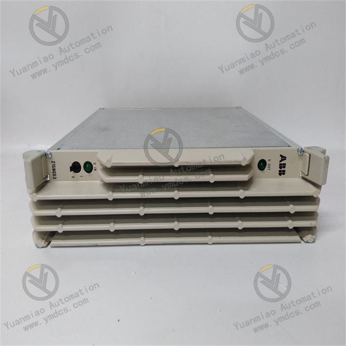
ABB 500PSM03 (complete order number 1MRB150038R0001) is a Power Supply Module (PSM) under the industrial‑control‑system product portfolio of ABB Ltd., Switzerland. It belongs to the I/O hardware family of ABB Procontrol / Advant / MOD series industrial control systems. Widely deployed in ABB DCS, SIS, turbine control and hydropower‑station control systems, it serves as the core power‑supply hardware delivering backplane power for control‑system racks.
Designed for industrial‑automation scenarios in power plants, petrochemical facilities, metallurgy, water treatment, rail transit and manufacturing industries, the module performs tasks including field‑AC‑power rectification, voltage regulation, filtering, backplane power feeding and power‑supply‑status monitoring. Under redundant‑configuration architecture, two 500PSM03 modules are commonly installed in parallel within one rack as hot‑standby partners. Upon failure of one unit, the remaining module can independently carry the full rack load without power interruption, switching transients or supply disturbance. It constitutes critical hardware guaranteeing power‑supply reliability for industrial control systems.
It has passed a full set of industrial‑grade tests: full‑load burn‑in, thermal cycling, vibration‑shock testing, dielectric‑withstand testing, electromagnetic‑interference evaluation, redundant‑switchover verification and load‑step‑change testing. Supporting 7×24‑hour year‑round continuous full‑load operation, it withstands harsh cabinet‑level operating conditions such as high enclosed‑space temperature, dust‑humidity exposure, thermal cycling, strong electromagnetic interference and mains‑voltage fluctuations. Given the massive global installed base of ABB control systems, 500PSM‑series power‑supply modules are critical power‑feed hardware. Spare‑parts provisioning, fault replacement and system maintenance of such modules are essential to sustain reliable operation of active plants, and the hardware is one of the key components for system retrofitting projects and strategic spare‑part stockpiling.
2. Functional Features
2.1 High‑Reliability Industrial Power Supply with Wide‑Input‑Voltage Adaptability
The 500PSM03 adopts industrial‑grade switching‑power‑supply topology and supports wide‑range AC input. It maintains stable DC output under conditions including mains‑voltage fluctuation, frequency offset and short‑term power dropout. Built‑in input rectifier, EMI filter, PWM high‑frequency converter, output rectifier and voltage‑regulation feedback loops deliver high‑output‑voltage accuracy, low ripple and fast dynamic response. It provides clean, stable, interference‑free DC power for CPU main‑boards, I/O modules and communication modules within the same rack, ensuring stable operation of digital circuits, analog circuits and communication circuits of the control system.
2.2 Redundant Hot‑Standby Power Feeding, No Interruption upon Single‑Module Failure
The module supports rack‑backplane redundant‑parallel architecture for ABB control systems: two or more 500PSM03 units are connected in parallel to a common backplane as hot‑standby partners. Each module integrates diode‑ORing circuitry or active current‑sharing circuits. A faulty module automatically disconnects from the backplane, and remaining modules seamlessly take over the full load with zero switching gap, zero‑voltage dip and zero disturbance. Maintenance personnel can hot‑swap faulty power‑supply modules online without system shutdown or cabinet de‑energisation, representing the core design for high power‑supply reliability of industrial control systems.
2.3 Galvanic Isolation between Input and Output for Strong Noise Immunity
A built‑in high‑frequency transformer provides complete galvanic isolation between input‑side and output‑side circuits, effectively blocking surges, ground‑loop currents and common‑mode interference propagating from the AC mains into the control‑system backplane. The input stage integrates varistors, surge suppressors and EMI filter circuits; the output stage incorporates π‑type filtering, TVS transient‑voltage suppression and overcurrent protection. It resists lightning‑induced transients, large‑equipment‑switching shocks, VFD harmonics and electrostatic discharge in complex industrial electromagnetic environments. It eliminates CPU reset, data loss, communication breakdown and unintended I/O actuation caused by power‑side anomalies propagating into the control system.
2.4 Output Overcurrent / Overvoltage / Short‑Circuit Protection with Auto‑Recovery
Comprehensive output‑protection mechanisms are implemented: overcurrent protection (automatic current limiting or current cutoff upon output‑current overload), overvoltage protection (automatic output shutdown when output voltage exceeds threshold), short‑circuit protection (automatic current limiting for output short‑circuit; auto‑recovery after fault clearance), over‑temperature protection (automatic derating or shutdown upon excessive internal module temperature. Under any abnormal output‑side condition, the module will not damage backplane hardware or field equipment. Normal output is restored automatically after fault removal without manual reset, supporting 7×24‑hour continuous‑system operation.
2.5 On‑Board Self‑Diagnostics and Status Indicators for Real‑Time Power‑Supply Supervision
Multi‑layer self‑diagnostics monitor input voltage, output voltage, output current, internal temperature and redundant‑parallel status. Multiple front‑panel LEDs provide real‑time indication of power‑supply‑healthy status, input‑voltage abnormality, output‑voltage abnormality, overload, fault and redundancy status. With dedicated ABB engineering software (e.g. Control Builder, ABB Ability, MOD Control, etc.), maintenance personnel can remotely retrieve power‑supply‑module diagnostic words, input/output voltage‑current readings, temperature values, redundancy status and fault codes to accurately locate root‑causes of power‑supply faults. On‑site manual measurement for every unit is unnecessary, greatly shortening troubleshooting and repair turnaround times for power‑supply failures.
2.6 Modular Debug‑Free Design for Efficient Operation‑Maintenance and Replacement
Adopting standardised modular plug‑in architecture for ABB industrial‑control systems, the module features precise rack alignment, easy assembly‑disassembly and secure latching, matching mechanical layout of standard ABB control cabinets. Thanks to standardised backplane connectors and redundant‑current‑sharing design, faulty power‑supply modules can be hot‑swapped online without system shutdown, rewiring or re‑configuration. The replacement unit automatically joins the redundant‑parallel power‑supply group and takes over the load seamlessly. Board dimensions, connector pin‑outs and front‑panel layout are compatible with other ABB‑series power‑supply modules, delivering high spare‑part universality.
3. Technical Specifications
3.1 Core Compatibility Parameters
| Item | Specification |
|---|---|
| Complete Order Number | 1MRB150038R0001 (500PSM03) |
| Brand | ABB (ABB Ltd., Switzerland) |
| Product Family | ABB 500PSM series / Procontrol / Advant / MOD control‑system power‑supply module |
| Module Type | Power Supply Module (PSM) |
| Supported Systems | ABB Procontrol / Advant / MOD series industrial control systems, DCS, SIS, turbine control, hydropower‑station control |
| Associated Hardware | Corresponding‑system rack backplane, CPU main‑boards, I/O modules, communication modules |
| Core Functions | AC‑input rectification & voltage regulation, backplane DC power feeding, redundant‑parallel hot‑standby, output protection, power‑supply self‑diagnostics |
| Redundancy Scheme | Multi‑module parallel redundancy; faulty module auto‑disconnect; remaining modules take over full load seamlessly |
| Typical Applications | DCS power feeding for power‑plant thermal‑process control, SIS power feeding for petrochemical plants, metallurgical‑process control, hydropower‑station monitoring, water‑treatment automation, manufacturing‑line control |
3.2 Electrical‑Performance Parameters
| Item | Specification |
|---|---|
| Input Voltage | Industrial‑grade wide‑range AC input, adaptable to field‑control‑power‑supply voltage classes |
| Output Voltage | System‑nominal DC‑voltage output; high accuracy, low ripple, fast dynamic response |
| Isolation Method | High‑frequency‑transformer galvanic isolation; complete electrical separation between input‑side and output‑side circuits |
| Protection Features | Built‑in overcurrent, overvoltage, short‑circuit and over‑temperature protection; input‑side EMI filtering, surge suppression and varistor protection |
| Redundant‑Parallel Operation | Diode‑ORing / active current‑sharing; faulty module auto‑disconnect; seamless load takeover |
| Interface Configuration | Industrial screw‑type terminals for field‑AC‑input; backplane connector delivering DC power to rack |
| Electrical Stability | 7×24‑hour continuous operation; free of output drift, false over‑temperature tripping and redundant‑parallel‑link anomalies |
| Self‑Diagnostics | Multi‑layer diagnostics covering input voltage, output voltage/current, temperature and redundancy status; fault‑LED indication and remote diagnostic‑word upload |
3.3 Environmental and Physical Parameters
| Item | Specification |
|---|---|
| Operating Temperature | Industrial wide‑temperature cabinet‑grade design for enclosed‑cabinet service conditions |
| Storage Temperature | Qualified for extreme‑temperature storage and transportation |
| Operating Humidity | 5 %‑95 %RH (non‑condensing); tolerant of dusty high‑humidity cabinet environments |
| Environmental Resistance | Dust‑proof, moisture‑resistant, oil‑tolerant, thermal‑ageing‑resistant, vibration‑resistant, high‑EMI‑immunity |
| Mounting Method | Plug‑in installation onto corresponding‑system standard racks; supports online hot‑swap replacement |
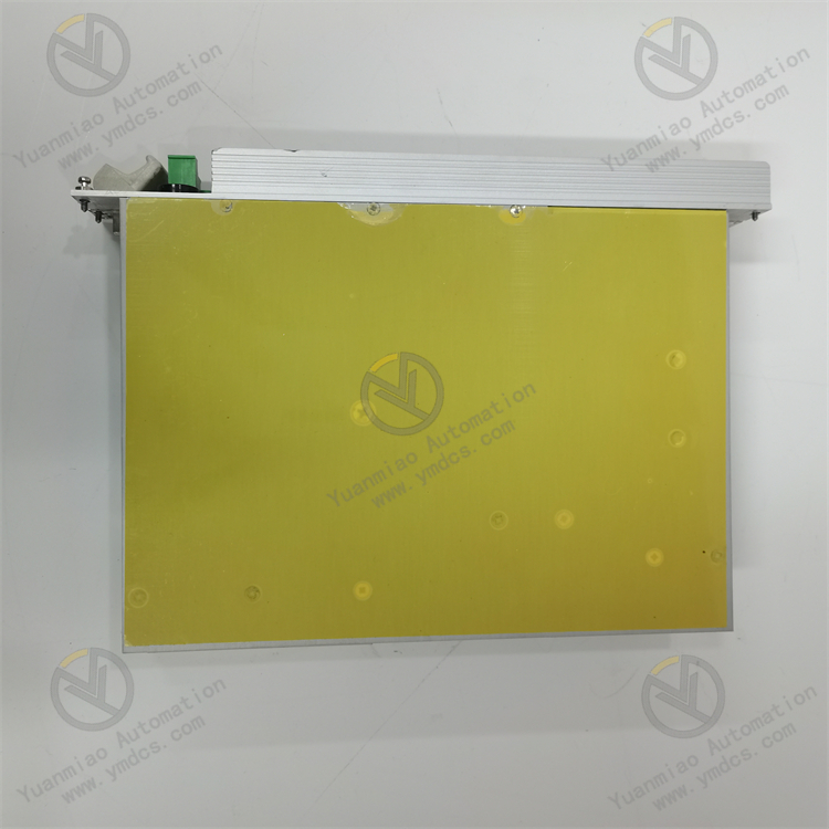
| Mechanical Construction | Industrial flame‑retardant reinforced PCB, metal housing; anti‑vibration, anti‑loosening, wear‑resistant, ageing‑resistant, flame‑retardant and moisture‑resistant |
4. Hardware Configuration and Structural Advantages
4.1 Core Hardware Configuration
The 500PSM03 power‑supply module adopts dedicated switching‑power‑supply hardware architecture for ABB industrial control systems. Key components include input‑EMI‑filter & rectifier circuits, PWM high‑frequency‑conversion circuits, high‑frequency‑transformer isolation unit, output‑rectifier & voltage‑regulation‑feedback circuits, output‑filter & protection circuits, redundant‑parallel‑ORing circuits, backplane‑power connector, status‑LED array and diagnostic‑communication circuits. Refined partitioned‑circuit design is implemented internally. High‑voltage‑input loops, high‑frequency‑conversion loops, low‑voltage‑output loops and digital‑diagnostic loops are fully isolated from one another, eliminating high/low‑voltage crosstalk, uneven heat dissipation and electromagnetic interference at hardware level.
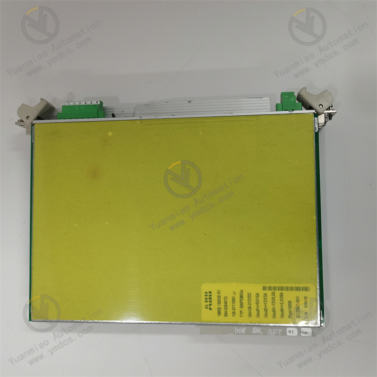
Core electronic components and power devices have passed strict original‑manufacturer screening and industrial qualification tests including full‑load burn‑in, thermal shock, vibration fatigue, high‑voltage insulation, electromagnetic‑interference evaluation, overload and short‑circuit testing. Optimised for long‑term unattended field‑site operation, mains‑voltage fluctuation and high‑temperature enclosed‑cabinet conditions. The rear‑side gold‑plated ABB‑system‑standard backplane connector ensures reliable mating with rack backplane for DC‑power delivery. The front panel hosts screw‑type field‑AC‑input terminal blocks and multi‑group status‑LED arrays for convenient field construction and maintenance. Reinforced metal‑shielded housing is adopted for the whole unit. Multi‑point mechanical fixing and thermal design for internal power components enable long‑term tolerance of cabinet‑level continuous vibration, thermal cycling, oil contamination and dust exposure.
4.2 Structural and Engineering‑Related Advantages
Featuring standardised compact modular architecture for ABB industrial‑control systems, the module fits densely‑populated cabinet power‑slot layouts with high space‑utilisation efficiency, secure installation and broad compatibility. Constructed with industrial flame‑retardant, moisture‑resistant and anti‑vibration reinforced metal housing, internal power loops and heat‑dissipation air ducts are multi‑point locked, sustaining long‑term exposure to cabinet‑level vibration, thermal cycling, humidity and dust. Clearly‑marked AC‑input terminals and backplane‑output interfaces greatly reduce risks of field‑wiring mistakes and lower power‑supply‑loop‑troubleshooting difficulty.
Faulty legacy modules can be replaced in‑situ without cabinet‑rack modification, control‑system‑logic alteration or plant‑system shutdown, substantially cutting costs for power‑supply‑system retrofitting, operation‑maintenance and emergency repair. Standardised hardware design unifies dimensions, terminal‑block layout, mounting method and commissioning software with other ABB‑series power‑supply modules. Spare‑part management, on‑site training and fault troubleshooting for maintenance staff are highly consistent, comprehensively meeting reliability‑guarantee requirements for long‑term stable power delivery of industrial‑control systems.
5. Operating Principle
The 500PSM03 implements a closed‑loop power‑supply workflow: field‑AC‑power input → EMI filtering & rectification → high‑frequency PWM conversion → transformer isolation & output rectification → voltage‑regulation feedback & redundant‑parallel operation → stable backplane power feeding → self‑diagnostics and protection. It achieves safe, stable and redundant conversion from field AC power to rack‑backplane DC power for ABB control systems.
During system operation, field industrial‑AC power (typically 220 V AC or 110 V AC control supply) is fed into front‑panel AC‑input terminals. It first passes through EMI‑filter circuits to suppress common‑mode and differential‑mode interference from mains, then is converted into DC‑bus voltage by rectifier bridge. DC‑bus voltage is delivered to PWM high‑frequency‑conversion circuits, where high‑frequency switching devices chop it into high‑frequency‑AC square‑waves and feed them into the high‑frequency transformer to realise galvanic isolation and voltage transformation between input‑side and output‑side circuits.
AC square‑waves from the transformer secondary are processed by output‑rectifier and π‑type‑filter circuits and converted into system‑nominal DC voltage. The voltage‑regulation‑feedback loop samples output voltage in real‑time and adjusts switching‑device duty‑cycle via the PWM controller to stabilise output voltage at nominal value regardless of input‑voltage fluctuation and load variation. Regulated DC power is delivered to rack backplane through the rear‑side backplane connector to power CPU main‑boards, I/O modules and communication modules within the same rack.
Under redundant‑parallel architecture, multiple 500PSM03 modules are connected in parallel to the same DC bus via backplane. Each module outputs independently through its ORing circuit. Under normal conditions, multiple modules share the load jointly. When one module fails or its output voltage deviates abnormally, the ORing circuit automatically disconnects the faulty module from backplane, and remaining modules take over the full load seamlessly with zero switching gap. Continuous on‑board self‑diagnostics monitor input voltage, output voltage/current, internal module temperature and redundant‑parallel status. Alarms are triggered via front‑panel LEDs and remote diagnostic‑word reporting upon anomaly detection. Maintenance personnel may hot‑swap faulty modules online; the replacement unit automatically joins the redundant‑parallel power‑supply group after power‑on.
6. Troubleshooting
6.1 Power‑Supply‑Module Fault Alarm or Abnormal Output
| Probable Cause | Diagnostic Approach | Remedial Action |
|---|---|---|
| Abnormal field‑AC‑input voltage, phase loss or excessive fluctuation | Measure voltage at AC‑input terminals; review module‑input‑voltage LED status and engineering‑software diagnostic readings | Troubleshoot field‑AC‑power‑supply loops; module auto‑recovers after supply anomaly is eliminated |
| Failure of internal power devices or output circuits inside module | Review output‑voltage measurements and LED status; compare outputs with the redundant peer module | Hot‑swap and replace 500PSM03 module per procedures; system power supply remains uninterrupted |
| Loose, oxidised backplane connector or retracted pins | Remove module completely; inspect gold‑plated fingers and backplane pins | Clean gold‑plated fingers and pins; re‑insert and latch module securely; repair backplane for retracted pins |
| Triggered internal over‑temperature or overload protection | Review module‑temperature diagnostic values; inspect cabinet heat dissipation and check for over‑load condition | Improve cabinet ventilation and heat dissipation; troubleshoot backplane short‑circuit and overload; replace module if necessary |
6.2 One Module Disengaged in Redundant‑Power‑Supply Configuration while System Remains Operational
| Probable Cause | Diagnostic Approach | Remedial Action |
|---|---|---|
| Hardware ageing or partial‑component failure of one 500PSM03 | Compare output voltage, current and temperature diagnostic values of both modules | Hot‑swap and replace faulty module online; system power supply is maintained undisturbed by the other unit |
| Fault in AC‑input loop (circuit‑breaker tripping, loose wiring) | Check AC‑input‑terminal voltage and upstream‑circuit‑breaker status of faulty module | Restore AC‑input power; tighten input terminals; module automatically resumes parallel‑supply operation |
| False triggering of ORing circuit or output protection | Review module diagnostic words and fault codes | Troubleshoot output‑side short‑circuit; replace module if required |
6.3 Overall Backplane Power Loss or System Reboot
| Probable Cause | Diagnostic Approach | Remedial Action |
|---|---|---|
| Simultaneous failure of all power‑supply modules or total loss of AC mains supply | Measure total field‑AC‑supply voltage; inspect LED status of all power‑supply modules | Restore total AC‑mains supply; replace all faulty power‑supply modules; reboot control system per procedures |
| Backplane‑output‑side short‑circuit or overload triggering protection of all modules | Measure backplane‑output‑to‑ground resistance after power‑off; troubleshoot I/O modules one‑by‑one | Isolate short‑circuit point; repair backplane short‑circuit fault; restore power supply |
| Fault of backplane connector or backplane wiring | Inspect physical condition of backplane connector and wiring; measure backplane‑output voltage | Clean or repair backplane connector; replace backplane in severe cases |