Description
1. Product Overview
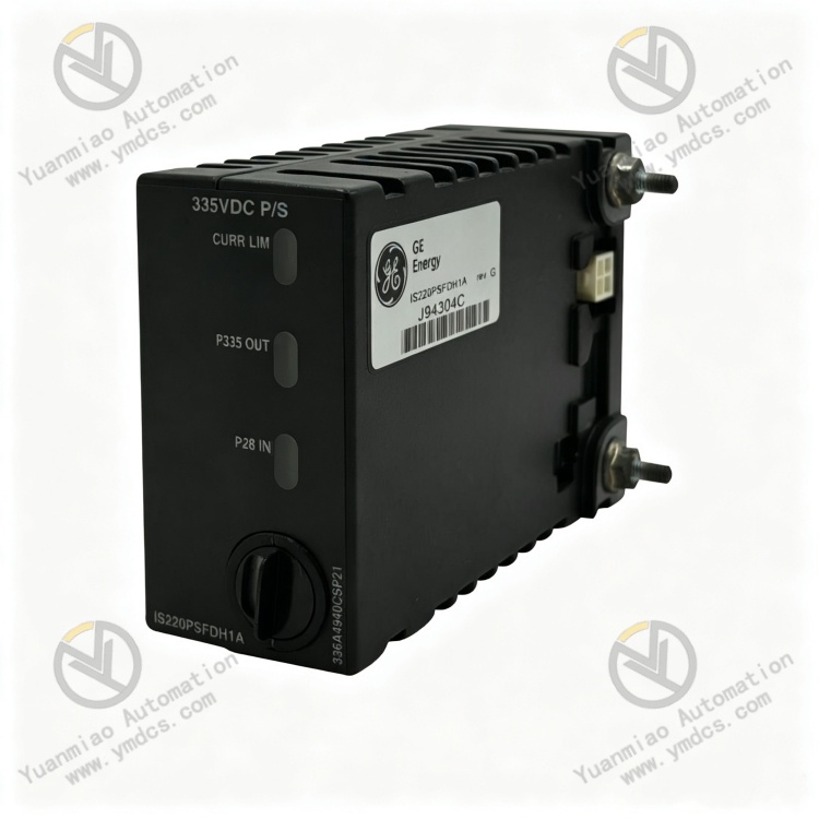
GE IS220PSFDH1A is an original‑equipment‑manufacturer (OEM) high‑voltage power‑supply module for flame detectors, developed and manufactured exclusively for the Mark VIe control system. As a core supporting power‑supply board for combustion‑monitoring systems of gas‑turbine and steam‑turbine generator sets, it is widely deployed in thermal‑power plants, gas‑fired combined‑cycle power stations, cogeneration plants and other electric‑power automatic‑control applications.
Custom‑built for gas‑turbine flame‑detection loops, this module delivers stable, high‑precision dedicated high‑voltage DC power supply to furnace flame detectors. It integrates electrical isolation, short‑circuit protection, voltage‑stabilization filtering, fault monitoring and other all‑in‑one functions to guarantee accurate flame‑signal acquisition and safe, reliable loop operation. Adopting an industrial‑grade isolated power‑supply architecture, the device features high voltage‑withstand capability, constant‑current output and powerful anti‑interference performance. It effectively avoids power‑supply anomalies and signal distortion caused by heavy electromagnetic interference, vibration and temperature variation in power‑plant environments. Validated under harsh power‑industry operating conditions, the module supports 7×24‑hour non‑stop continuous operation. It serves as a standard core component for new‑project deployment, replacement of ageing flame‑power modules and stability‑upgrade retrofits of flame‑detection systems within GE Mark VIe gas‑turbine control installations.
2. Technical Parameters
2.1 Basic Specifications
‑ Product Model: IS220PSFDH1A ‑ Product Series: GE IS220 Mark VIe Gas‑Turbine Control‑System Power‑Supply Series
‑ Product Type: High‑Voltage DC Power‑Supply Module Dedicated to Flame Detectors
‑ Core Function: High‑voltage power supply, electrical isolation, loop protection and power‑supply status monitoring for gas‑turbine furnace flame detectors
‑ Compatible Systems: Full‑range GE Mark VIe control systems for gas turbines and steam‑turbine generator units
‑ Compatible Equipment: Fully matched with OEM gas‑turbine flame‑detector detection loops and all furnace flame‑monitoring assemblies
‑ Mounting Method: Embedded slot‑mounting in standard cabinets, compliant with standardized GE cabinet layout
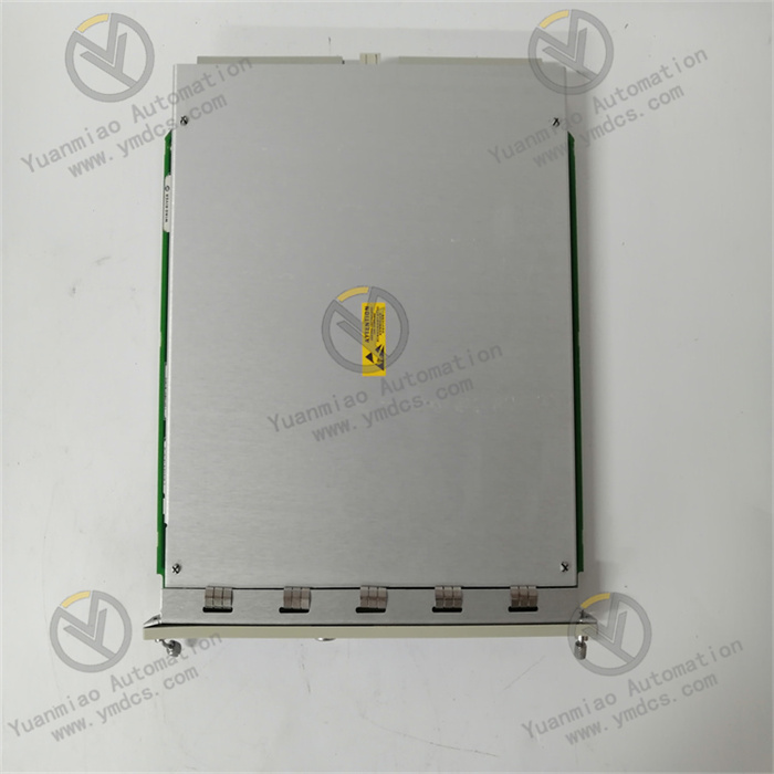
‑ Structural Features: Compact encapsulated board design with regular dimensions and convenient wiring; fully solid‑state construction with no moving mechanical parts; excellent anti‑ageing and anti‑vibration properties with no long‑term performance degradation
2.2 Electrical Output Parameters
‑ Output Voltage: Standard 335 V DC high‑voltage output with ±5 % accuracy, stable operating range: 318 V DC ~ 352 V DC, matching the rated operating voltage of flame detectors
‑ Output Current: 7 mA constant‑current output mode, with continuous short‑circuit protection, adapted to the low‑current high‑precision operating characteristics of flame‑detection loops
‑ Isolation Withstand Voltage: Electrical isolation between input and output, insulation withstand voltage up to 1700 V DC, effectively isolating interference between high‑voltage and low‑voltage loops and eliminating electric‑leakage and cross‑talk faults
‑ Voltage‑Stabilization Performance: Built‑in high‑precision voltage‑stabilizing circuit automatically compensates for voltage fluctuations; zero output drift and zero voltage drop under variable‑load conditions
‑ Protection Mechanism: Integrated continuous short‑circuit protection, over‑voltage protection, over‑current protection and no‑load protection, providing comprehensive protection against flame‑detection‑loop faults
‑ Filtering Characteristics: On‑board high‑frequency noise‑reduction filtering circuit suppresses mains‑supply ripple, voltage spikes and electromagnetic noise to deliver clean high‑voltage output power
2.3 Interface & Diagnostic Parameters
‑ Terminal Blocks: Partitioned dedicated terminal blocks with separate ports for power input, high‑voltage output and ground connection, delivering clear wiring layout and convenient maintenance
‑ Status Indicators: On‑board LED indicators for operation status and fault alarms, providing local visual display of module power‑supply, fault and loop‑abnormality conditions
‑ System Diagnostic Function: Supports upper‑level diagnostic communication with the Mark VIe system; uploads operational data including output voltage, loop current, short‑circuit faults and no‑load anomalies
‑ Fault‑Monitoring Capability: Real‑time detection of over‑voltage, under‑voltage, over‑current, short‑circuit, no‑load, loop‑open‑circuit and other full‑dimension fault states
‑ Functional Characteristics: Plug‑and‑play operation with no complex program configuration required; automatically adapts to flame‑detection‑loop operating conditions upon power‑up, natively compliant with system control logic
2.4 Environmental & Protection Specifications
‑ Operating Temperature: ‑30 ℃ ~ +65 ℃ wide industrial temperature range, suitable for sustained high‑temperature, constant‑temperature operation inside enclosed power‑station cabinets
‑ Storage Temperature: ‑40 ℃ ~ +75 ℃, satisfying requirements for long‑distance transportation, idle‑state warehousing and spare‑part storage for projects
‑ Operating Humidity: 5 %‑95 % RH non‑condensing; resistant to humid, dusty and lightly‑oily ambient conditions commonly encountered in power‑station facilities
‑ EMC Compliance: Meets the highest‑level power‑industry electromagnetic‑compatibility standards and provides immunity against strong electromagnetic interference generated by gas‑turbine variable‑frequency drives and high‑power equipment
‑ Protection Design: Insulating anti‑corrosion coating applied to the printed‑circuit board; special insulation protection for high‑voltage loops to prevent oxidation, electric leakage and high‑voltage breakdown
‑ Operational Reliability: Fully solid‑state hardware architecture with no mechanically wearable components; 7×24‑hour continuous operation without parameter drift or performance degradation
3. Product Functions and Core Advantages
3.1 Core Product Functions
Dedicated high‑voltage power supply for flame detectors
Custom‑built for gas‑turbine furnace flame‑detection loops, the module delivers stable high‑precision 335 V DC high‑voltage power that precisely matches the operating parameters of flame detectors. It provides compliant and stable core power supply for furnace flame‑signal acquisition, operating‑condition identification and combustion‑state monitoring, ensuring continuous normal operation of flame‑detection loops.
High‑voltage electrical‑isolation protection
With 1700 V DC high‑level electrical‑isolation design, the module completely separates the low‑voltage input side from the high‑voltage output side. It eliminates cross‑talk between high‑voltage and low‑voltage loops, ground‑potential‑difference interference and electric‑leakage risks, effectively protecting downstream flame detectors and upstream control‑system boards and avoiding high‑voltage breakdown and electrical short‑circuit faults.
Constant‑current voltage‑stabilization and power‑supply conditioning
Adopting a constant‑current output and high‑precision voltage‑stabilization architecture together with multi‑stage noise‑reduction filtering circuits, the module automatically compensates for mains‑supply and load‑side voltage fluctuations and filters high‑frequency industrial noise and transient surges. It supplies clean and stable high‑voltage power and prevents flame‑signal jumps, detection distortion, false flame‑alarm triggers and missed flame detection caused by power‑supply disturbances.
Multi‑layer hardware safety protection for the full loop
Equipped with multiple hardware‑based protection mechanisms including continuous short‑circuit, over‑voltage, over‑current and no‑load / open‑circuit protection for each output loop. When faults such as short‑circuit, wire breakage, abnormal load or out‑of‑limit voltage occur in the flame‑detection loop, the module immediately initiates protective latching, cuts off abnormal output, stops fault propagation and safeguards the whole combustion‑monitoring system.
Real‑time operating‑condition monitoring and fault tracing
The module continuously monitors its own running status, high‑voltage output parameters and loop‑load conditions. Fault information is transmitted simultaneously to local on‑board indicators and the upper‑level host system, enabling precise location of loop short‑circuits, wire breakages, voltage anomalies and equipment failures. It provides accurate data support for maintenance, troubleshooting and root‑cause analysis of combustion‑system faults.
Native system interoperability
Fully adapted to the GE Mark VIe gas‑turbine control‑system architecture, its power‑up sequencing, output accuracy and fault‑feedback logic fully comply with OEM specifications. It interfaces seamlessly with flame‑detection cards, signal‑acquisition modules and system interlock logic and reliably supports dynamic operating scenarios including unit startup‑shutdown cycles and load‑swing transitions to guarantee reliable operation of combustion‑monitoring and interlock‑protection functions.
3.2 Core Advantages
‑ Dedicated high‑voltage power supply for improved detection accuracy
Custom‑designed 335 V DC high‑voltage constant‑current output optimized for flame‑detector operating conditions delivers stable and precise parameters. It fundamentally resolves flame‑detection deviations and unintended interlock trips triggered by unstable low‑accuracy generic power supplies and greatly enhances gas‑turbine combustion‑monitoring accuracy.
‑ Superior electrical safety via high‑level isolation design
1700 V DC high‑withstand‑voltage electrical isolation eliminates hardware‑level risks of high‑/low‑voltage cross‑talk, high‑voltage leakage and equipment breakdown. Adapted to complex high‑voltage, high‑interference power‑plant environments, it substantially raises the electrical‑safety grade of the combustion‑control system.
‑ Excellent fault‑resistance performance with sustained short‑circuit hold‑up protection
Continuous short‑circuit protection removes the requirement for system shutdown and reset after temporary loop short‑circuits; normal output is automatically restored once the fault is cleared. This significantly reduces unplanned outages and equipment shutdown risks originating from field wiring faults and improves overall unit operational stability.
‑ Full OEM compatibility, zero‑risk retrofitting
Fully compliant with GE’s original Mark VIe specifications including pin‑out definitions, electrical parameters, communication logic and physical mounting dimensions. Direct drop‑in replacement of legacy flame‑power modules requires no modification to system programs, wiring schemes or interlock‑logic configuration, delivering simple upgrade deployment with zero compatibility risks.
‑ Zero‑configuration, easy‑to‑maintain design with low total‑cost‑of‑ownership
Plug‑and‑play deployment eliminates complex configuration work. Fault conditions are locally visible, diagnosable and traceable; routine visual inspections are sufficient for long‑term service. The maintenance‑free solid‑state hardware requires no periodic calibration, cutting power‑station labour and overhaul costs.
‑ Power‑plant‑grade industrial quality with project‑ready acceptance compliance
Validated under long‑term harsh operating conditions at large gas‑turbine power stations. The module fully meets acceptance specifications for combustion‑control‑system hardware in gas‑turbine and combined‑cycle facilities and satisfies compliance requirements for both new‑build and retrofit power‑plant projects.
4. Typical Application Scenarios
‑ Gas‑Turbine Control Systems: High‑voltage power supply, loop isolation and safety protection for furnace flame detectors in Mark VIe installations at large gas‑fired power stations
‑ Combined‑Cycle Power‑Plant Systems: Power‑supply hardware matching and signal‑stability optimization for combustion‑monitoring systems of gas‑steam combined‑cycle units
‑ Cogeneration Unit Systems: Dedicated high‑voltage power supply and fault protection for flame‑detection loops of gas‑turbine sections at thermal‑power cogeneration plants
‑ Industrial Captive‑Power‑Station Systems: Power‑supply hardware for flame‑monitoring systems of self‑owned gas‑turbine generator‑sets at large industrial sites and energy‑production bases
‑ Combustion‑Safety Protection Systems: Monitoring and protection unit guarding against short‑circuit, over‑voltage and electric‑leakage faults in gas‑turbine flame‑detection loops
‑ Legacy‑System Upgrade‑and‑Retrofit Projects: Replacement of ageing flame‑power modules and accuracy‑&‑safety enhancement upgrades for existing Mark VIe flame‑detection systems
5. Installation, Commissioning and Maintenance Guidelines
Before installation, fully disconnect the main cabinet power supply and module power feed. Allow sufficient time for capacitor discharge, then remove dust, oil and debris from the cabinet interior. Insert the module securely into its designated slot and fasten firmly to prevent board loosening, poor‑contact wiring connections and high‑voltage power‑supply anomalies caused by equipment vibration.
Strictly separate low‑voltage input loops, high‑voltage output loops and grounding circuits. Route cables in compliance with OEM electrical drawings. Lay high‑voltage and low‑voltage cables on segregated wiring layers; route high‑voltage loops independently with reinforced insulation protection to avoid high‑voltage faults caused by cross‑connection or insulation damage.
Never energize the module with over‑rated input voltage; do not perform short‑circuit or no‑load tests on the high‑voltage output. After wiring completion, verify loop continuity and insulation performance one by one to ensure matched flame‑detector load conditions. Prohibit long‑term no‑load, over‑loaded or short‑circuit operation.
During initial commissioning, complete insulation testing, output‑voltage‑accuracy verification and simulated‑load trials. Validate each function including voltage‑stabilized output, electrical isolation, short‑circuit protection and fault‑alarm logic to confirm reliable functional operation and normal flame‑signal acquisition.
For routine maintenance, periodically inspect module indicator‑lamp status, tightness of high‑voltage wiring terminals and cable‑insulation integrity. Monitor output voltage values, loop currents and fault logs via the upper‑level host system to identify hidden risks such as insulation ageing, voltage drift and concealed cable damage at an early stage.
Regularly clean accumulated dust and oil deposits from the module surface and cabinet interior. Maintain good cabinet ventilation together with dry, dust‑free, moisture‑proof and corrosion‑resistant ambient conditions. Give priority to insulation‑condition maintenance of high‑voltage connectors and prevent high‑voltage leakage, surface creepage and breakdown faults triggered by dust and dampness.
Faulty modules shall be replaced exclusively with an original‑equipment GE IS220PSFDH1A unit. After replacement, restore the original wiring topology and loop‑configuration settings. Perform insulation testing, high‑voltage output calibration, full‑system joint commissioning and flame‑signal testing, and confirm that power‑supply accuracy, protection‑logic behaviour and detection performance remain identical to pre‑replacement conditions.