Description
1. Product Overview
Full Model: 200-595-045-114
Manufacturer: VIBRO-METER
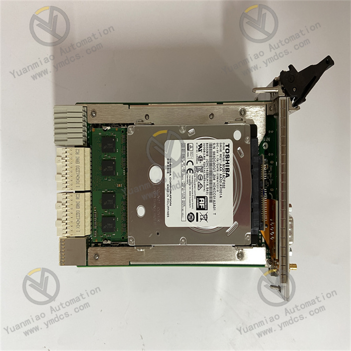
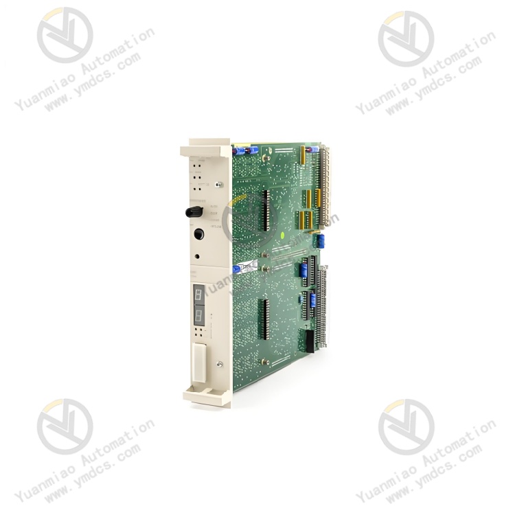
Product Name: VM600 Rack-mounted System CPU Main Control Module / System Control Processor Card
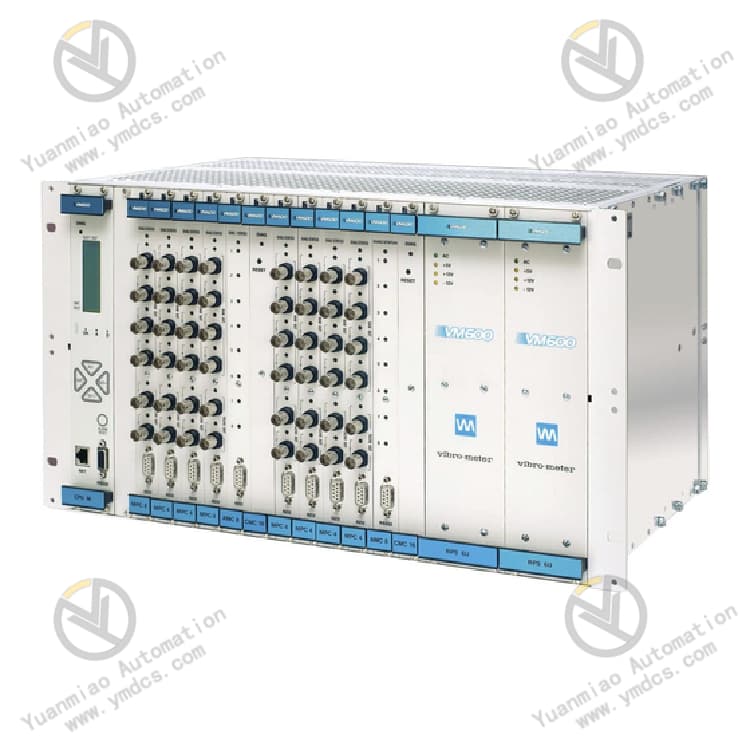
Product Description: Model 200-595-045-114 is a dedicated CPU main control module for the VIBRO-METER VM600 machinery protection and condition monitoring system, acting as the core computing and communication hub of the entire vibration monitoring system. The module undertakes system logic operation, data collection & aggregation, fault judgment, alarm and interlock management, data storage and host communication interaction. It centrally controls all sub-modules installed in the rack, including vibration input cards, output cards and speed measurement cards.
This high-reliability industrial version is designed for critical rotating equipment such as thermal power units, gas turbines, compressors, fans and pumps. It realizes continuous monitoring and equipment protection logic control for parameters including unit vibration, shaft displacement, rotating speed and temperature. Featuring powerful computing capability, high stability, long-term drift-free performance, built-in self-diagnosis and support for redundant fault-tolerant architecture, it serves as the key main control hardware for commissioning, interlock protection, data tracing and condition analysis of large unit vibration monitoring systems. Only original identical replacement is allowed; general industrial CPU modules cannot be used as substitutes.
2. Core Functions
Main control and computation for the whole system, coordinating all IO monitoring cards in the rack to uniformly acquire unit process data such as vibration, shaft displacement, rotating speed, key phase signal and temperature.
Embedded equipment protection logic algorithms that detect faults including excessive vibration, abnormal displacement and overspeed in real time, and trigger alarm and interlock protection actions.
Large-capacity data buffering and storage for long-term archiving of trend data, peak values, event records, fault logs and interlock action records, meeting requirements of unit condition tracing and fault analysis.
Multi-protocol communication output enabling data interaction with DCS, PLC, upper monitoring software and local touch screens to support remote monitoring, parameter configuration and system diagnosis.
Global system self-diagnosis function that continuously monitors rack power supply, bus links, sub-card status and communication status to accurately locate card faults, communication anomalies and configuration errors.
Supports system configuration management, parameter calibration, alarm threshold setting and interlock logic configuration. On-line parameter modification can be performed without unit shutdown, suitable for unit operation, maintenance and commissioning.
- High-reliability fault-tolerant operation compatible with system redundant architecture. Fault isolation can be achieved when single module abnormality occurs to maximize continuous stable operation of the unit monitoring system.
3. Technical Features
Industrial high-reliability main control architecture: Customized for large rotating machinery protection systems, equipped with high-frequency processors offering sufficient computing power and fast response. It processes multi-channel high-frequency vibration data simultaneously without data delay or packet loss.
Integrated system coordination capability: Centrally manages all VM600 monitoring cards within the rack to realize centralized data computation, unified alarm logic and integrated communication output, featuring concise system architecture and consistent logic.
Comprehensive data recording and traceability capability: Supports millisecond-level event logging, fault snapshots and trend storage, which accurately reconstruct abnormal unit processes and provide data support for equipment fault analysis, maintenance rectification and unit optimization.
Multiple software and hardware protection mechanisms: Built-in hardware watchdog, power-fail protection and encrypted data storage prevent system crash, data loss and logic disorder, adapting to 7×24-hour uninterrupted operation of units.
Complete compatibility and expandability: Fully compatible with all VM600 series IO cards, rack backplanes and system software. It allows later channel expansion, logic upgrade and function expansion with strong equipment scalability.
- Non-destructive in-situ replacement for maintenance: Standard 6U rack slot installation. Interfaces, protocols and firmware are fully compatible with same-series versions. No modification to unit interlock logic is required after replacement; commissioning can be completed simply by synchronizing configuration, greatly improving maintenance efficiency.
4. Specification Parameters
| Item | Parameter |
|---|---|
| Model | 200-595-045-114 |
| Product Series | VIBRO-METER VM600 Machinery Protection & Monitoring System |
| Product Type | System CPU Main Control Processor Module |
| Core Function | System logic operation, data aggregation, alarm & interlock, communication forwarding, system configuration management |
| Applicable Equipment | Critical rotating machinery: steam turbines, gas turbines, centrifugal compressors, large fans, pumps etc. |
| Hardware Architecture | Standard 6U rack-mounted plug-in design |
| System Power Supply | 24VDC backplane power supply |
| Communication Interfaces | Ethernet, serial port, supporting standard industrial communication protocols |
| Operating Temperature | -20℃~+70℃ |
| Storage Temperature | -40℃~+80℃ |
| Ambient Humidity | 5%~95%RH (Non-Condensing) |
| Core Functional Characteristics | High-speed data computation, event recording, fault snapshot, global self-diagnosis, on-line configuration, interlock logic control |
| Operating Characteristics | Low failure rate, drift-free measurement, data retention upon power loss, electromagnetic interference resistance, continuous non-stop operation |
| Mounting Method | Fixed installation in standard VM600 rack backplane slot, supporting in-situ replacement |
| Maintenance Features | Supports on-line debugging, parameter backup & restoration, fault code tracing, on-line configuration without unit shutdown |
5. Working Principle
The module receives 24VDC operating power from the VM600 rack backplane. After power-on, it automatically completes hardware self-test, bus initialization, rack card scanning and system configuration loading. It enters main control operation mode after confirming normal power supply, bus communication, sub-card status and communication links.
During operation, the CPU module collects raw monitoring data including vibration, displacement, rotating speed and temperature from all IO cards via internal high-speed bus, and executes data filtering, arithmetic conversion, engineering value conversion and logic judgment. According to preset alarm thresholds and interlock logic, the module judges unit operating conditions in real time: monitoring data is continuously uploaded when parameters are normal; local alarms, remote notifications and interlock protection outputs are triggered immediately once parameters exceed limits or equipment abnormalities occur to ensure unit safety.
Meanwhile, the module continuously records system operation logs, event sequences, fault snapshots and parameter modification records to realize full traceability of unit conditions. The hardware-level self-diagnosis mechanism monitors overall system status continuously. Once bus anomalies, sub-card faults, communication interruption or parameter abnormalities are detected, alarms will be uploaded immediately with fault locations marked, ensuring long-term, stable and accurate operation of the complete machinery monitoring and protection system.
6. Common Faults & Solutions
1. No system communication, upper host cannot connect, system fully offline
Causes: CPU module crash or firmware exception; damaged communication cable or port; incorrect IP address and communication parameters; poor contact of backplane bus; loss of core module firmware.
Solutions: Restart the CPU module for system reset; verify and restore correct communication parameters and IP settings; inspect and replace communication cables, repair faulty ports; re-seat the module to improve backplane contact; re-flash original firmware if program error occurs. Replace the module if the fault persists.
2. Single or multiple channels stop updating data, sub-cards show offline status
Causes: Abnormal CPU bus scanning; backplane bus failure; damaged unrecognized sub-cards; missing or corrupted system configuration; stuck CPU computing threads.
Solutions: Refresh system hardware configuration and re-scan rack devices; inspect backplane bus links and power supply; reset corresponding IO cards; restart the CPU module to recover bus scheduling. Replace the CPU main control module if hardware failure cannot be repaired.
3. Frequent system alarms, logic misjudgment and disordered data
Causes: Abnormal CPU program operation and calculation errors; incorrect configuration parameters and messy threshold settings; hardware aging and data drift after long-term operation; program disturbance caused by electromagnetic interference.
Solutions: Check and organize system alarm thresholds and interlock configuration; isolate on-site interference sources and optimize cabinet grounding; back up parameters, restore factory settings and reload configuration. Replace original spare parts if frequent disorder and logic failure indicate module aging.
4. Abnormal module indicator lights after power-on, failure to start normally
Causes: Unstable or insufficient backplane power supply; damaged internal power circuit of the module; corrupted firmware; circuit anomaly caused by dust and moisture accumulation.
Solutions: Test rack power supply voltage and retry after voltage stabilization; clean dust and moisture on the module; re-flash firmware. Replace the module if normal self-test and startup cannot be achieved, indicating hardware damage.
5. System fails to commission after CPU module replacement, configuration mismatch
Causes: Incompatible firmware version of new module; original configuration parameters not imported; mismatched rack hardware address; inconsistent bus protocol version.
Solutions: Match corresponding original firmware version; import backup configuration and synchronously calibrate system parameters; verify rack hardware address and bus settings; restart the system for overall initialization to complete commissioning.