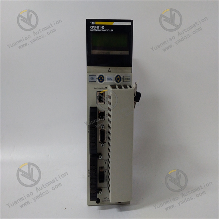
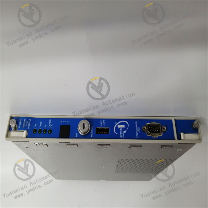
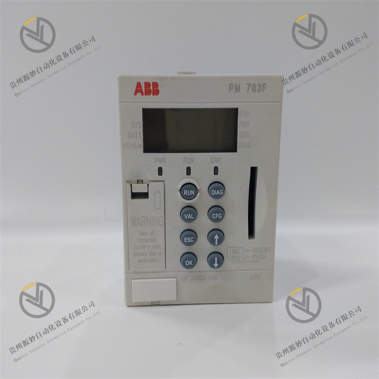
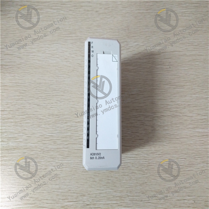
Description
Features: System affiliation: It is part of the ABB ProControl P13 series. This series is a system used for industrial automation control, aiming to provide reliable control and monitoring solutions for various industrial processes. Function and purpose: It is usually a digital input/output module, used to connect field devices and controllers in industrial control systems. It can receive digital signals from field devices (such as buttons, switches, sensors, etc.) and transmit them to the controller for processing. At the same time, it can also output digital control signals issued by the controller to field devices (such as relays, indicator lights, etc.) to achieve the control of the devices. Technical parameters: Generally, it has a certain number of input and output channels. For example, it may have 16 or 32 input/output channels. The input channels can accept digital signals within a specific voltage range, such as 24V DC signals. The output channels can provide corresponding driving capabilities to control external devices. It has good electrical isolation performance, which can ensure the electrical safety and signal integrity between the field devices and the control system. It usually has high anti-interference ability and can work stably in complex industrial electromagnetic environments. Shape size and installation: The module has a compact shape design and is suitable for installation in standard industrial control cabinets. It usually adopts a rail-mounted installation method, which is convenient and quick, and easy for maintenance and replacement. Diagnosis and maintenance: It has a self-diagnosis function and can monitor its own working status, such as channel failures, power failures, etc., and feedback fault information to users through indicator lights or communication with the control system, which is convenient for timely maintenance and troubleshooting. Technical parameters: Input characteristics Input signal types: It supports multiple input signal types, such as analog input (AI) and digital input (DI). Analog input can usually receive continuously changing signals from sensors, such as 4-20mA current signals or 0-10V voltage signals output by sensors for temperature, pressure, flow, etc. Digital input can receive switch signals to detect the status of devices, such as the start and stop status of motors, the open and close status of valves, etc. Number of input channels: Generally, it has multiple input channels and can connect multiple sensors or signal sources simultaneously to achieve the monitoring of multiple physical quantities or device statuses. The specific number of channels may vary depending on different models and configurations. Commonly, there are 8 channels, 16 channels, etc. Output characteristics Output signal types: It includes analog output (AO) and digital output (DO). Analog output can be used to control actuators, such as setting the frequency of frequency converters, controlling the opening of regulating valves, etc. It usually outputs 4-20mA current signals or 0-10V voltage signals. Digital output is used to control devices such as relays and contactors to achieve functions such as starting and stopping control and logical switching of devices. Number of output channels: Similarly, it has multiple output channels to meet the control requirements of multiple devices or actuators. The number of output channels also varies depending on the model. Commonly, there are 4 channels, 8 channels, etc. Accuracy Analog input accuracy: For analog input channels, it usually has high accuracy, generally reaching ±0.1% - ±0.5% FS (full scale). This means that within the entire input signal range, the error between the measured value and the actual value can be controlled within a small range, ensuring the accuracy of physical quantity measurement. Analog output accuracy: The accuracy of analog output is also quite high, generally ±0.5% - ±1% FS, which can accurately output control signals to the actuators to achieve precise control. Operating temperature range: It can usually work normally within a wide temperature range, generally -40°C - 85°C. This enables the module to adapt to different industrial environments and can operate stably whether beside high-temperature industrial furnaces or in low-temperature outdoor environments. Power requirements: It generally requires a DC power supply, and the common supply voltage is 24V DC. The module has good power adaptability and can work normally within a certain voltage fluctuation range, usually allowing a power voltage fluctuation range of ±10% - ±20%. Communication interface: It has multiple communication interfaces, such as Profibus-DP, Modbus-RTU, etc., which can conveniently communicate and exchange data with other devices or control systems. Through these communication interfaces, the module can upload the collected input signal data to the upper computer monitoring system and receive control instructions from the upper computer to achieve remote control and adjustment of the output signals. Common faults and solutions: 1. Communication fault Fault phenomenon: The module cannot communicate normally with other devices, such as being unable to read or write data in the control system. Fault cause: Loose communication interface, incorrect communication parameter settings, damaged communication line, electromagnetic interference, etc. Solution: First, check whether the communication interface is firmly connected. If it is loose, re-plug it to ensure a good connection. Confirm whether the communication parameter settings match those of other devices in the system, including parameters such as baud rate, data bits, stop bits, and parity. If there are errors, modify them according to the correct settings. Check whether the communication line is damaged, open-circuited or short-circuited. If it is damaged, the line needs to be replaced. In addition, check whether there are strong electromagnetic interference sources around, and take measures such as shielding and filtering to reduce electromagnetic interference. 2. Abnormal output signal Fault phenomenon: The analog or digital output signal does not match the expectation, such as incorrect signal values, unstable signals or no signal output. Fault cause: Faults in the internal signal processing circuit of the module, incorrect output wiring, load problems, etc. Solution: Check whether the output wiring is correct and ensure that the wiring is firmly connected to the correct terminals. Check whether the load is normal, whether there are overload, short-circuit or open-circuit conditions. If there are problems, repair or replace the load. If the wiring and load are normal, it may be that the internal signal processing circuit of the module has a fault. In this case, contact professional maintenance personnel to repair or replace the module. 3. Power fault Fault phenomenon: The module cannot work normally, and there may be phenomena such as the power indicator not lighting up or the module overheating abnormally. Fault cause: Input power not connected, abnormal power voltage, fault in the internal power circuit of the module, etc. Solution: First, check whether the input power is normal and measure whether the power voltage is within the working range allowed by the module. If the power voltage is too low or too high, adjust the power to meet the requirements of the module. If the power voltage is normal, check whether the power wiring of the module is firmly connected and whether there are loose or open-circuit conditions. If the external power and wiring are both okay, it may be that the internal power circuit of the module has a fault, and the module needs to be sent for repair or replaced. 4. Module overheating Fault phenomenon: The surface temperature of the module is too high, possibly exceeding the normal working temperature range, and even causing the module to automatically shut down for protection. Fault cause: Poor heat dissipation, too high ambient temperature, fault of internal components of the module, etc. Solution: Check whether the installation location of the module has good ventilation and whether there is enough heat dissipation space around. Clean the surface of the module and the surrounding area of dust and debris to improve the heat dissipation conditions. At the same time, check whether the ambient temperature exceeds the allowable working temperature range of the module. If necessary, take measures to reduce the ambient temperature, such as adding ventilation equipment or adjusting the installation location. If both the heat dissipation and the ambient temperature are normal, it may be that the internal components of the module have a fault, and professional personnel need to be contacted for maintenance. 5. Incorrect input signal Fault phenomenon: The input signal received by the module is inconsistent with the actual input, such as a large deviation in the analog input value or an incorrect digital input status. Fault cause: Incorrect input wiring, sensor failure, damage to the input channel of the module, etc. Solution: Check whether the input wiring is correct and ensure that the wiring is firmly connected to the correct input terminals. Check whether the connected sensor is working normally, which can be verified by measuring the output signal of the sensor or replacing the sensor. If the sensor is normal, it may be that the input channel of the module has a fault. Try to connect the input signal to other available input channels to determine whether it is a single-channel fault. If it is determined that the input channel of the module is faulty, contact professional personnel to repair or replace the module.