Description
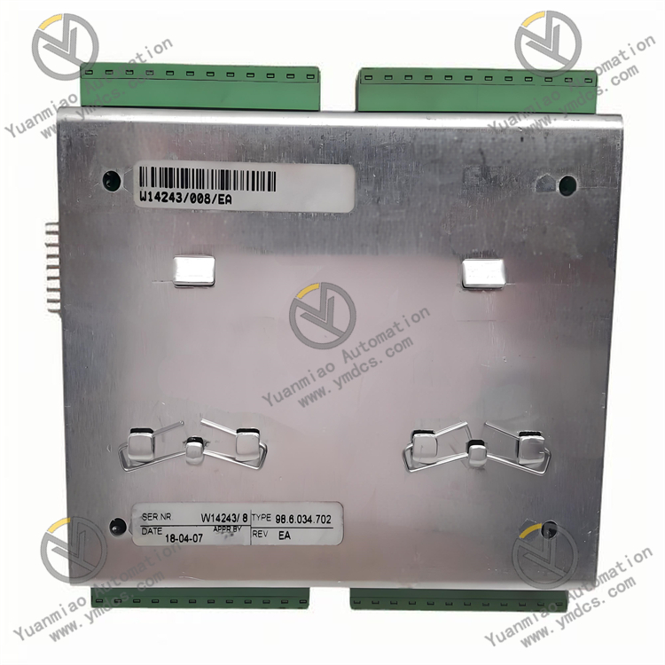
Praxis 98.6.034.702
I. Overview
Taking a pharmaceutical production workshop as an example, this module can connect analog sensors such as temperature and pressure sensors, collect key parameters in the fermenter in real time, and transmit the data to the central control system; at the same time, it receives instructions from the control system and controls the operating status of equipment such as stirring motors and valves through digital output channels, ensuring that the fermentation process is always in the optimal process conditions and guaranteeing the stability of drug quality.
II. Technical Parameters
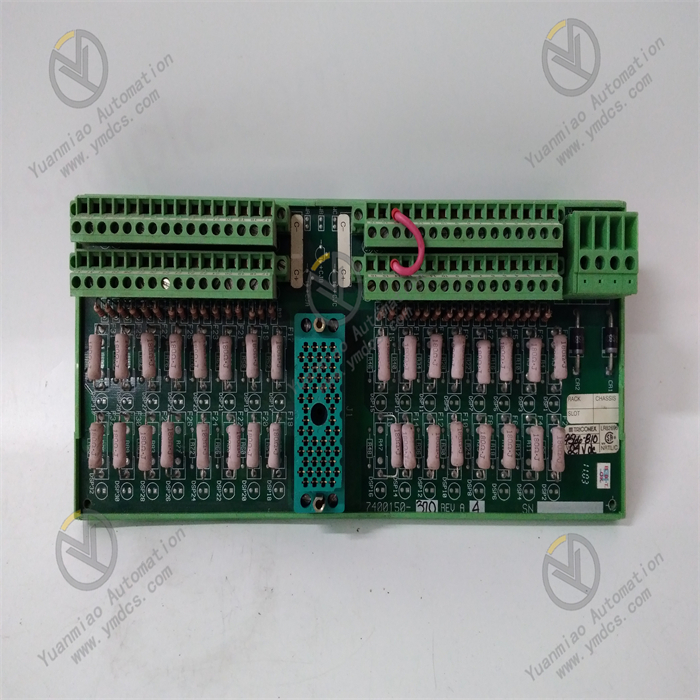
Digital input channels: Equipped with 8 digital inputs, supporting dry contacts and NPN/PNP type wet contact signals. The input voltage range is 10-30V DC, and the response time is ≤ 0.5ms, which can quickly capture changes in the on-off state of equipment, such as signals from limit switch triggering and button operations.
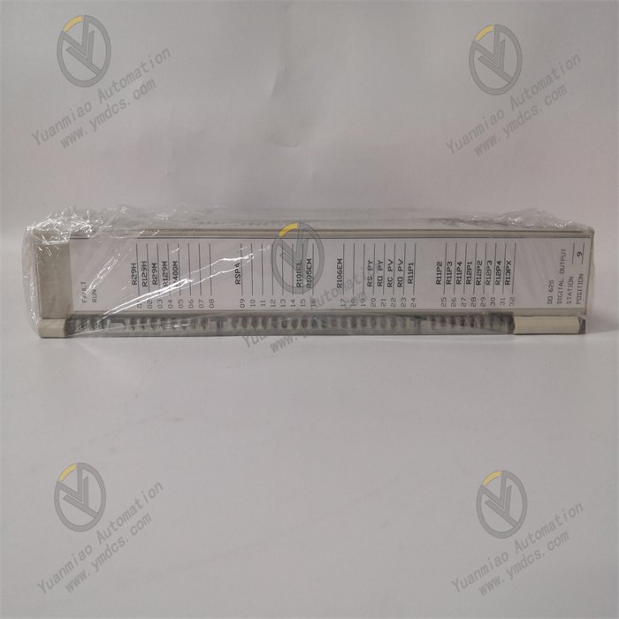
Digital output channels: Includes 8 digital outputs, each with a maximum output current of 2A. The output voltage is consistent with the power supply voltage (24V DC), which can directly drive loads such as solenoid valves and small motors, meeting the control needs of medium-power equipment.
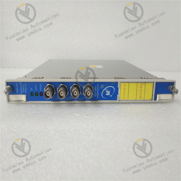
Analog input channels: Has 4 analog inputs, supporting 4-20mA DC and 0-10V DC signal types, with a resolution of 16 bits, a sampling rate of 10Hz, and a measurement accuracy of ±0.1% FS. It can accurately collect signals of continuously changing physical quantities such as temperature, pressure, and flow.
Analog output channels: Equipped with 4 analog outputs, supporting 4-20mA DC and 0-10V DC signals, with a resolution of 16 bits and an output accuracy of ±0.2% FS. It can perform continuous and precise opening or speed adjustment of equipment such as control valves and frequency converters.
Isolation performance: Optoelectronic isolation is adopted between input, output and power supply, with an isolation voltage ≥ 3000V AC (for 1 minute). Digital and analog channels are isolated from each other, effectively suppressing electromagnetic interference in industrial sites and ensuring the accuracy of signal transmission.
Environmental adaptability: The operating temperature range is -30°C to +75°C, and the relative humidity is 5%-95% (no condensation), enabling stable operation in extreme temperature and humid environments; it can withstand vibration of 10-500Hz with an acceleration of 15g and impact of 50g (11ms half-sine wave), adapting to mechanical vibration and impact in industrial sites.
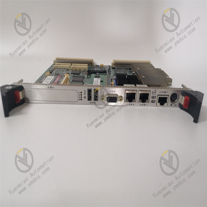
Communication interface: Integrates 1 Ethernet interface (supporting MODBUS TCP/IP protocol) and 1 RS-485 interface (supporting MODBUS RTU protocol), with a maximum data transmission rate of 100Mbps. It can flexibly connect to control systems such as PLCs and upper computers, realizing high-speed data interaction and remote monitoring.
Dimensions: Adopts standard DIN rail mounting, with dimensions of 140mm × 90mm × 65mm (length × width × height). It has a compact structure, saving installation space in the control cabinet.
III. Functional Features
High-precision signal acquisition and output: The 16-bit resolution analog channels ensure the accuracy of signal acquisition and output. The measurement and output accuracies reach ±0.1% FS and ±0.2% FS respectively, meeting the strict control requirements for process parameters in industries such as pharmaceuticals and food, and ensuring the stability of the production process.
Fast response and real-time control: The digital input response time is ≤ 0.5ms, and the analog sampling rate is 10Hz, which can quickly capture subtle changes in on-site signals, ensuring that the control system can obtain key information in a timely manner and respond, improving the real-time control performance of the system.
Multiple isolation and anti-interference: Through high-voltage isolation design and mutual isolation between channels, it effectively blocks the propagation path of electromagnetic interference, and can still maintain stable operation in industrial environments with strong interference sources such as frequency converters and motors, avoiding signal distortion or misoperation.
Flexible communication and compatible integration: It supports both Ethernet and RS-485 communication, and is compatible with MODBUS TCP/IP and RTU protocols. It can seamlessly connect with control systems of different brands and types, adapting to diversified industrial network architectures and facilitating system expansion and upgrading.
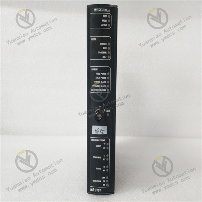
Intelligent diagnosis and status monitoring: The surface of the module is equipped with status indicators for each channel and communication indicators, which can intuitively display the operating status; it has a built-in self-diagnosis function, which can real-time monitor problems such as power failures and communication abnormalities, and upload fault information to the control system through the communication interface, facilitating quick troubleshooting.
IV. Common Faults and Solutions
Possible causes: Interference introduced by poor shielding of signal cables; incorrect channel calibration parameters; abnormal output signal of the sensor; failure of the analog acquisition circuit.
Solutions: Check whether the shielding layer of the signal cable is well grounded, and replace it with a shielded twisted pair; recalibrate the analog channel and restore the default parameters; use a multimeter to detect the output signal of the sensor to confirm whether it is within the normal range; if the circuit is faulty, replace the damaged components or the module.
No output from digital output channel
Possible causes: Protection action caused by overload of the output channel; loose or poor contact of the terminal block; damage to the output drive circuit; short circuit of the load burning the channel.
Solutions: Disconnect the load, check whether the channel returns to normal, replace the load with a matching capacity or add an intermediate relay; re-tighten the terminal block to ensure good contact; use a multimeter to detect the conductivity of the output circuit, and replace the damaged driver chip or module; check the load short-circuit point, and replace the damaged channel or module after repair.
Unstable or interrupted communication
Possible causes: Poor contact or disconnection of network cables; incorrect settings of communication parameters such as IP address and baud rate; damage to the communication interface; excessive network load or interference.
Solutions: Check the connection of network cables or RS-485 cables and replace damaged cables; check and unify the communication parameters of the module and the control system; replace the communication interface module or the entire module; reduce the number of network devices, add network switches or repeaters, and stay away from strong interference sources.
Module fails to start or crashes frequently
Possible causes: Unstable power supply voltage or voltage lower than 24V DC; loose or poor contact of power supply wiring; error in the internal program of the module; ambient temperature exceeding the operating range.
Solutions: Check the output of the power supply to ensure that the voltage is stable within 24V DC±10%; re-plug the power supply wiring and tighten the terminals; reset or upgrade the firmware of the module; improve the ventilation and heat dissipation conditions of the installation environment to ensure that the temperature is within the range of -30°C to +75°C.