Description
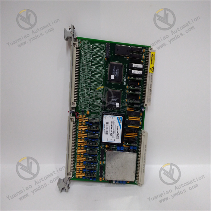
TRICONEX 3008N
I. Overview
II. Technical Parameters
Processing capability: Equipped with a 32-bit Motorola MPC860 processor with an operating frequency of 50 MHz, it has a fast computing speed and can efficiently process complex safety control logic and massive real-time data. It supports multiple programming languages such as ladder diagrams, function block diagrams, and structured text, facilitating engineers to flexibly carry out program development and debugging according to the needs of different industrial scenarios.
Communication capability: Supports multiple mainstream industrial communication protocols such as Modbus TCP/IP, EtherNet/IP, and PROFIBUS, enabling high-speed and stable data interaction with upper monitoring systems, HMI (Human-Machine Interface), and other intelligent devices. The communication interface adopts photoelectric isolation technology, with strong anti-electromagnetic interference ability, ensuring communication stability and data transmission accuracy in complex industrial electromagnetic environments.
Safety certification: Passed SIL3 (Safety Integrity Level 3) certification, strictly follows international authoritative safety standards such as IEC 61508 and IEC 61511, reaches the top level in the industry in terms of safety performance, and can meet the extremely strict requirements for safety control in high-risk industrial scenarios.
III. Functional Features
High-speed safety interlock response: It has an extremely short response time to input signals, can quickly identify abnormal changes in equipment operating status within milliseconds, and quickly output control commands according to preset safety logic. In emergency situations, such as detecting dangerous situations such as overpressure and overtemperature of equipment, it can instantly trigger key safety actions such as emergency shutdown and cutting off energy supply, minimizing the losses caused by accidents.
Online configuration and maintenance: Supports online programming, parameter modification, and program downloading without interrupting system operation, effectively reducing production downtime caused by system maintenance. Engineers can conveniently configure and monitor the module remotely through dedicated software, which greatly improves the convenience and work efficiency of system maintenance.
IV. Common Faults and Solutions
Causes of failure: The communication cable may have poor contact, such as loose connectors, or the cable may be damaged, disconnected, etc.; incorrect settings of network parameters such as IP address, subnet mask, and communication protocol, resulting in failure to communicate normally with the upper system or other equipment; hardware failure of the communication interface, such as damage to the interface chip.
Solutions: Carefully check the connection of the communication cable, re-plug the connector, and if the cable is damaged, replace it with a new one in time; carefully check and reset the network parameters to ensure that it is in the same network segment as the upper system and all communication parameters match correctly; if it is determined that the communication interface hardware is faulty, the communication interface module can be replaced. If you do not have the conditions to replace it yourself, contact professional and technical personnel for maintenance in time.
Causes of failure: The input line may be open or short-circuited, resulting in blocked signal transmission; abnormal power supply to front-end equipment such as sensors, making it unable to output signals normally; the input channel itself is damaged, affecting signal reception and processing.
Solutions: Use a multimeter to test the on-off and voltage of the input line, find the broken or short-circuited point and repair it; check the power supply of the sensor to ensure it is normal. If the sensor is damaged, replace it with a new one in time; adopt the replacement method, connect the normally working module to the same input line to determine whether the input channel is damaged. If damaged, replace the corresponding module.
Causes of failure: A short circuit occurs in the output line, and the module starts the protection mechanism to stop output after detecting the short circuit; actuators, such as relays and solenoid valves, fail to receive or execute output commands; the output channel is damaged, making it impossible to output effective control signals.
Solutions: Comprehensively check the output line to find and eliminate the short-circuit fault point, so that the module can resume normal output function; detect the working status of the actuator to see if it is damaged, and replace the faulty actuator if necessary; if it is judged that the output channel is damaged, the module can be replaced or the corresponding parts can be repaired.
Causes of failure: Unstable power supply voltage, exceeding the normal 24V DC range. Too high or too low voltage may affect the normal operation of the module; the module runs for a long time, with excessive internal temperature and poor heat dissipation, resulting in abnormal performance; errors occur during program operation or memory failure, affecting the normal operation of the module.
Solutions: Use professional instruments to detect the power supply voltage to ensure that it is stable at 24V DC; check the heat dissipation of the module, clean the dust in the heat dissipation holes, improve ventilation conditions, and add auxiliary heat dissipation equipment such as cooling fans if necessary; read fault information through programming software. If it is a program error, re-download the correct program; if the memory is suspected to be faulty, try to repair or replace the memory. If it is a hardware problem after investigation, contact the manufacturer to replace the module in time.