Description
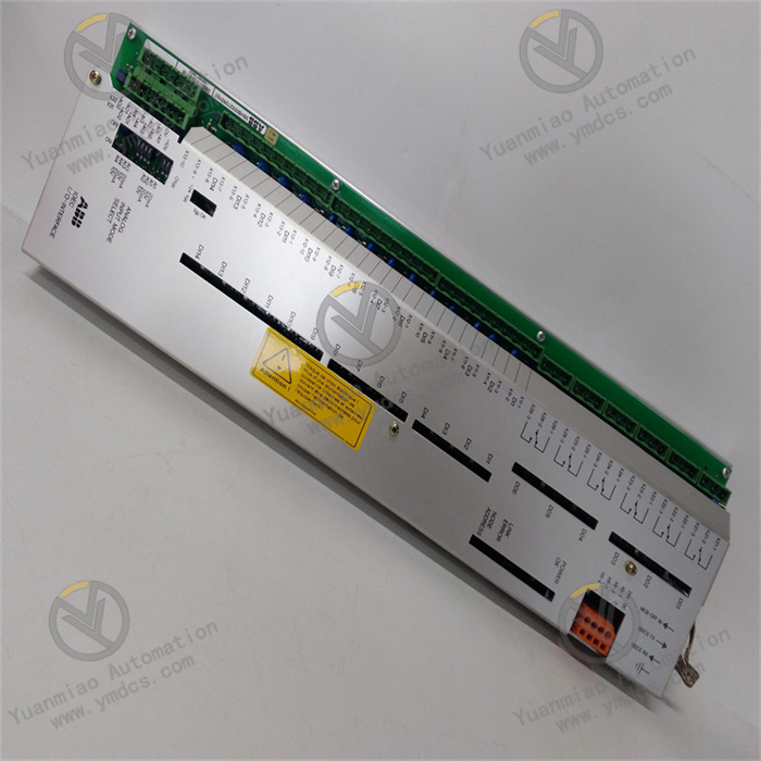
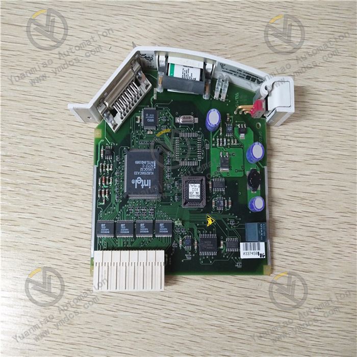
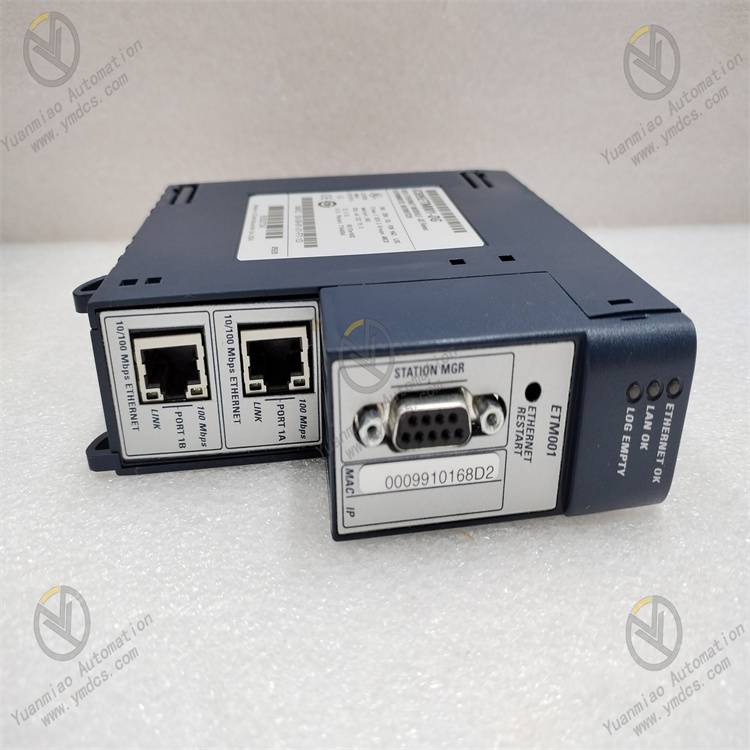
GE IC695CRU320-EJ
I. Overview
II. Technical Parameters
Memory Configuration: Equipped with 1GB DDR3 memory, providing sufficient space for program operation and data caching, which can support the smooth operation of large control programs and the temporary storage of massive real-time data. At the same time, it has 4GB of flash memory for storing important information such as user programs, system configurations, and historical data, ensuring stable storage and quick access to data.
Power Requirements: Supports dual redundant power inputs with an input voltage range of 100-240V AC, enabling stable operation within a wide voltage range and improving the power supply reliability of the system. The maximum power consumption of each power module is 50W, ensuring stable power support even in redundant working mode.
Communication Interfaces: Equipped with 2 10/100/1000Mbps Gigabit Ethernet interfaces, supporting protocols such as TCP/IP and Modbus/TCP to realize high-speed data transmission and remote communication. It also has 2 USB 2.0 interfaces for program downloading, data backup, and equipment debugging, as well as 1 RS-232 serial interface for convenient communication with some traditional devices.
Dimensions: Adopting a compact design with a width of 160mm, a height of 220mm, and a depth of 280mm, it is easy to install in standard industrial cabinets, saving installation space.
III. Functional Features
Powerful Control Capability: Supports multiple international standard programming languages, such as Ladder Diagram (LD), Structured Text (ST), Function Block Diagram (FBD), Sequential Function Chart (SFC), etc., facilitating engineers to select appropriate programming languages according to different control needs and quickly develop complex control programs. It has rich functions such as high-speed counting, pulse output, PID control, and motion control, which can realize precise control of various physical quantities and equipment.
Advanced Diagnosis and Maintenance Functions: Equipped with perfect self-diagnosis and remote diagnosis functions, which can real-time monitor the operating status of the control unit itself, power modules, communication interfaces, I/O modules, etc. When a fault is detected, it can send alarm information in a timely manner through Ethernet, indicator lights, etc., and record detailed information such as fault codes and fault time, facilitating maintenance personnel to quickly locate and eliminate faults, and reducing maintenance costs and time.
Hot-Swappable Function: Some modules support hot swapping, such as power modules and communication modules. Faulty modules can be replaced during system operation without shutting down the system, reducing system maintenance time and improving system availability.
IV. Common Faults and Solutions
Possible Causes: Errors or interruptions in the synchronous data between the main and standby control units; faults in the redundant communication link, such as damaged connecting cables or loose interfaces; faults in the standby control unit itself; power module faults causing the standby unit to be unable to supply power normally.
Solutions: Check the synchronous data link between the main and standby units to ensure normal data transmission, and the synchronization status can be viewed through special diagnostic tools. Check whether the redundant communication cables are intact and the interfaces are firmly connected, and replace the cables if necessary. Replace the standby unit with a normal one for testing to determine if it is a standby unit fault. Check whether the power module output of the standby unit is normal to ensure that the standby unit can receive stable power supply.
Possible Causes: Physical damage to the Ethernet interface or serial interface; faults in communication cables, such as broken network cables or poor contact of USB cables; incorrect communication parameter settings, such as IP address conflicts, incorrect subnet mask or gateway settings; mismatched communication protocols.
Solutions: Check whether the communication interface is physically damaged, and replace the corresponding interface module if damaged. Replace the communication cable to ensure that the cable is firmly connected and intact. Check the communication parameter settings to ensure that parameters such as IP address, subnet mask, and gateway match the network environment to avoid conflicts. Confirm that the protocol used is consistent with that of the communication device, and reconfigure the protocol parameters if not.
Possible Causes: Input voltage exceeding the specified range; internal circuit damage of the power module; loose or poor contact of the power connection line; poor heat dissipation causing the power module to overheat.
Solutions: Check whether the input voltage is within the range of 100-240V AC to ensure stable voltage. If the power module is damaged, replace it with a new one. Check the power connection line, re-plug and fasten the connection plug to ensure good contact. Clean the heat dissipation holes of the power module and ensure that the cooling fan works normally to avoid power failure caused by overheating.
Possible Causes: Logical errors or loopholes in the program; incorrect settings of variables or addresses used in the program; abnormal external input signals leading to abnormal program execution; insufficient memory causing program operation interruption.
Solutions: Use programming software to check and debug the program, find logical errors and variable setting errors in the program through the online monitoring function, and correct them. Check whether the external input signals are normal to eliminate the impact of sensor faults or signal interference. Optimize the program by deleting unnecessary data and codes to free up memory space. If the memory is still insufficient, consider upgrading the memory module.
Possible Causes: The module is not correctly installed in the rack slot, resulting in poor contact with the backplane; the module itself is faulty; the rack or backplane is faulty and cannot communicate with the module; the system firmware version is too low to support the module.
Solutions: Reinstall the module into the rack slot to ensure firm installation and good contact with the backplane. Replace with a spare module for testing. If the spare module can be recognized, it indicates that the original module is faulty and needs to be replaced. Check whether the rack or backplane is damaged, and replace them if necessary. Upgrade the system firmware to the latest version to ensure that the system supports the module.


