Description
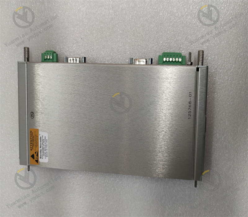
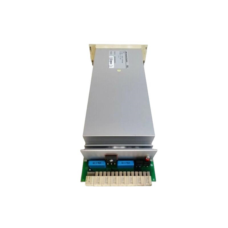
ABB SR511 3BSE000863R1
I. Overview
The SR511 3BSE000863R1 is a safety relay module belonging to the Safety Relay series, primarily used in industrial safety control systems to implement safety functions such as emergency stop, safety door monitoring, and two-hand control. Complying with safety standards like IEC 61508 and ISO 13849, this module ensures rapid cut-off of hazardous outputs during equipment anomalies through redundant design and fault detection mechanisms, preventing safety accidents. It is suitable for scenarios with high safety requirements, such as mechanical manufacturing, automotive production lines, and chemical equipment, serving as a core component for constructing safety loops.
II. Functional Features
High Safety Level Certification
- Meets safety levels SIL 3 (IEC 61508) and PL e (ISO 13849), supporting the highest safety integrity requirements.
- Equipped with dual-channel redundant circuits, it real-time monitors self-faults (e.g., contact adhesion, coil failure) and alarms via indicator lights.
Multi-Scenario Safety Function Support
- Emergency Stop (E-STOP): Connects to emergency stop buttons to quickly cut off equipment power when triggered.
- Safety Door Monitoring: Detects safety door switch status and immediately stops hazardous actions when the door is opened.
- Two-Hand Control: Collaborates with two-hand buttons to ensure both hands are away from hazardous areas during operation.
- Light Curtain/Grating Protection: Interlocks with safety light curtains to stop equipment when personnel enter hazardous areas.
Flexible Interfaces and Configuration
- Supports 4-8 safety inputs (e.g., button, sensor signals) and 2-4 safety outputs (relay contacts).
- Enables input/output logic configuration (e.g., normally closed/normally open contacts, self-holding mode) via DIP switches or external modules.
High-Reliability Design
- Mechanical life: Contacts withstand over 10 million operations, adapting to high-frequency usage scenarios.
- Operating temperature range: -25°C to +70°C, resistant to vibration (10-500Hz, 5g) and shock (30g, 11ms), meeting industrial environment requirements.
III. Technical Parameters
| Parameter Category | Specific Indicators |
|---|---|
| Power Supply Voltage | 24V DC (±10%), power consumption ≤5W |
| Input Channels | 4 safety inputs (dry contact/PNP/NPN compatible), response time ≤10ms |
| Output Channels | 2 safety relay outputs (normally open + normally closed contacts), contact capacity: 250V AC/10A, 30V DC/10A |
| Safety Characteristics | Diagnostic coverage (DC) ≥99%, safe failure fraction (SFF) ≥99% |
| Communication Interfaces | Optional MODBUS RTU or PROFIsafe interfaces (requires external communication modules) |
| Physical Dimensions | 94mm × 45mm × 110mm (width × height × depth), weight approx. 0.3kg |
| Protection Level | IP20 (suitable for installation in control cabinets) |
| Certification Standards | CE, UL, TÜV (SIL 3/PL e), IEC 61508, ISO 13849 |
IV. Working Principle
The core of the SR511 safety relay realizes safety functions through redundant circuit design and fault detection mechanisms, with the workflow as follows:
Signal Acquisition and Logic Judgment
- Receives safety input signals (e.g., emergency stop button press, safety door opening) and simultaneously detects signal status via dual-channel circuits.
- Internal logic circuits process input signals (e.g., self-holding, interlocking) to ensure compliance with safety logic (e.g., forcing output disconnection when an emergency stop signal is triggered).
Safety Output Control
- In normal conditions, safety output relays remain closed to allow equipment operation; during anomalies (e.g., input signal triggering or internal faults), relays quickly disconnect to cut off the equipment power circuit.
- Output contacts adopt Force-Guided Contact structures to ensure contact status matches coil signals, avoiding safety failures caused by contact adhesion.
Fault Diagnosis and Alarm
- Built-in monitoring circuits real-time inspect input/output loops, power voltage, and relay status. When faults are detected:
- Abnormalities are indicated via LED lights (e.g., FAULT, OK);
- Fault signals are output to external systems (e.g., PLC) to trigger alarms or shutdowns.
V. Common Faults and Solutions
| Fault Phenomenon | Possible Causes | Solutions |
|---|---|---|
| FAULT light always on | Abnormal input signal (e.g., emergency stop button not reset) | Check if all safety input devices (e.g., emergency stop buttons, safety doors) are reset to ensure the input loop is closed. |
| Output contact adhesion or circuit short | Power off and use a multimeter to detect output contact continuity; replace the relay module if adhesion occurs. | |
| Safety output inactive | Input loop open (e.g., loose cable) | Check input cable connections and use a multimeter to measure input terminal voltage (normally 24V DC). |
| Configuration logic error (e.g., DIP switch setting error) | Verify the module's DIP switch settings (e.g., input type, self-holding mode) and reconfigure according to the manual. | |
| Unusual relay noise or overheating | Oxidation due to frequent contact operation or overload | Check if the load current exceeds the contact capacity (≤10A); replace the relay or reduce the load; clean the contact surface. |
| Power indicator not lit | Loose power connection or abnormal voltage | Check power cable interfaces, measure input voltage (24V DC±10%), and replace faulty power modules. |
VI. Extended Application Scenarios
The SR511 is often used with ABB Safety PLCs (such as the AC500-S safety controller), safety light curtains, emergency stop buttons, and other devices. Typical scenarios include:
- Mechanical processing: Safety door monitoring and emergency stop protection for stamping machines and injection molding machines;
- Automotive manufacturing: Light curtain protection and two-hand control loops in production line robot areas;
- Chemical equipment: Reactor emergency shutdown systems to prevent leakage or overload faults;
- Logistics warehousing: Safety passage access control and equipment interlocking in automated stereo warehouses.