Description
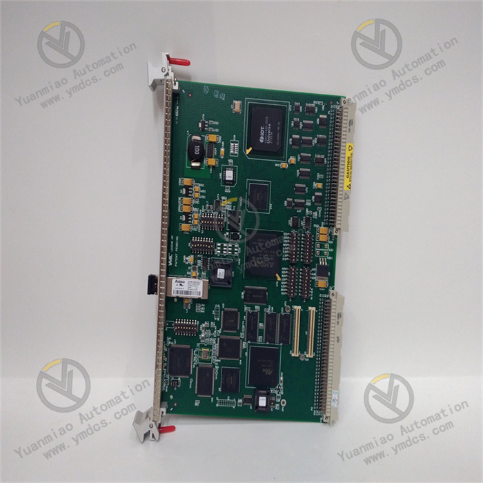
VMIC VMIVME-1182
I. Basic Information
Model: VMIVME-1182
Brand: VMIC (GE Fanuc / Abaco Systems)
Product Line: 6U VME bus intelligent isolated digital input board with 64 channels, designed for power protection, nuclear control and safety critical process systems. It integrates local pre-processing function to support millisecond SOE sequence of event recording, COS status change detection and pulse accumulation, widely used in power plant DCS, relay protection fault recording systems.
Product Positioning
VMIVME-1182 is a 64-channel opto-isolated DI board with on-board intelligent processor. It realizes local signal debounce, edge capture, time tagging and event caching to reduce VME bus load. With 1500VDC high channel isolation, it complies with ANSI/IEEE C37.90.1 surge standard when matched with VMIVME-3459 suppression panel. It collects switch status of high-voltage switchgear, protection relays and field actuators, providing accurate time-sequence fault data for power system accident tracing and equipment condition monitoring.
Hardware Architecture
Standard 6U VME single-layer PCB with three-proof coating, divided into five core units:
- On-board intelligent pre-processing processor: 1ms global scan, local event latch and pulse counting, independent of host CPU for signal filtering and edge detection.
- 64-channel independent opto-isolation array: each channel with isolated optocoupler and programmable hardware debounce circuit, compatible with AC/DC wide-range input signals.
- High-speed event cache RAM: stores millisecond SOE timestamp records and pulse cumulative values (0~65535 per channel), preventing data loss before host reading.
- VME32 bus interface: supports 8/16/32-bit data transmission, user-configurable interrupt level and access permission, ROAK interrupt acknowledge mechanism.
- AMP high-density front connector with surge protection expansion interface, meeting power industry overvoltage protection requirements with matched suppression panel.
Mounting Specification
Vertical 6U standard VME rack installation, compatible with 19-inch industrial VME chassis and MVME series CPU boards. It has passed IEC anti-vibration, humidity cycling and wide-temperature aging tests.Dimension (H×W×D): 233.35mm × 160mm × 25mm, net weight: 0.5kg.
Compatible Systems
- VME Host Hardware: MVME162, MVME172, MVME2700 series embedded controllers, standard 6U VME industrial chassis
- Accessories: VMIVME-3459 surge suppression panel, AMP crimp terminals, twisted shielded signal cables
- Software Environment: VxWorks / QNX real-time OS, UIOC driver suite, power SOE configuration tool
- Upper Monitoring: Power plant DCS, relay protection fault information station, SCADA dispatching system, fault recorder analysis platform
- Application Fields: Thermal/hydraulic/nuclear power station monitoring, substation automation, rail transit interlock, chemical ESD safety control system
Product Characteristics
- 64 independent opto-isolated DI channels with per-channel software parameter configuration for trigger edge, debounce time and working mode.
- Native millisecond SOE timestamp function to meet power industry fault sequence audit and relay protection timing verification requirements.
- Wide AC/DC input range (5~250VDC / 4~240VAC), directly compatible with passive/active field contact signals without signal conversion modules.
- 1500VDC dielectric isolation between channels and VME bus, strong common-mode interference immunity to avoid high-voltage surge damage to host system.
- On-board pulse accumulation up to 65535 counts per channel, suitable for flow meter, speed pulse local statistical acquisition.
- Flexible VME interrupt and access permission configuration, supports multi-master VME architecture and multi-board synchronous event reporting.
- Industrial wide-temperature three-proof design, stable 7×24h continuous operation in harsh electromagnetic control rooms.
II. Technical Specifications
2.1 Electrical & Isolation Parameters
- VME Backplane Power: +5VDC, typical power 4.2W, max operating current 840mA
- Digital Input: 64 opto-isolated channels, per-channel programmable
- Input Voltage Range: 5~250VDC / 4~240VAC (optional 5~60VDC / 110/240VAC version)
- Dielectric Withstand Voltage: 1500VDC 1min between channel-channel, channel-ground, channel-VME bus
- Scan Resolution: 1ms global cycle interval
- Debounce: software configurable per channel
- Pulse Count Range: 0 ~ 65535 pulses per channel
2.2 Function & Bus Parameters
- Core Functions: COS status change detection, millisecond SOE timestamp recording, pulse accumulation, edge capture
- Trigger Mode: Disable / Rising Edge / Falling Edge / Any Edge (per channel software selectable)
- VME Bus: VME32, 8/16/32-bit data transfer, ROAK interrupt acknowledge
- Interrupt: user-defined VME interrupt priority, vector interrupt event reporting
- Access Mode: Standard/Short Address, Supervisory, Non-Privileged, UIOC protocol compatible
- Event Storage: On-board RAM batch cache for SOE records, bulk upload to host to reduce bus load
2.3 Environmental Specifications
- Operating Temperature: 0℃ ~ +65℃; rugged version: -40℃ ~ +85℃
- Storage & Transport Temperature: -40℃ ~ +85℃
- Relative Humidity: 5%~95%RH, non-condensing, no corrosive gas or heavy dust
- Vibration Standard: IEC 60068-2-6, 0.7g continuous vibration horizontally & vertically
- EMC Compliance: ANSI/IEEE C37.90.1 surge standard (with VMIVME-3459), IEC61000-6-2
- Protection Class: Bare board IP20, IP30 in sealed metal control cabinet
2.4 Mechanical Parameters
- Form Factor: Standard 6U VME (233.35mm × 160mm × 25mm)
- Net Weight: 0.5kg
- Mounting: Vertical slot installation in 19-inch VME rack with front locking lever
- PCB: FR4 flame-retardant material, full-area three-proof anti-corrosion coating
- Interfaces: Front AMP high-density connector, rear 96-pin gold-plated VME bus connector
III. Key Features
3.1 64-Channel Isolated Switching Signal Centralized Acquisition
64 fully opto-isolated channels realize galvanic isolation between field high-voltage primary loop and VME host system, collecting circuit breaker position, protection trip contact, equipment fault alarm and remote/local switching signals. Per-channel hardware debounce eliminates contact bounce and electromagnetic false triggering to guarantee accurate status acquisition.
3.2 Millisecond SOE Sequence of Event Recording
On-board processor attaches 1ms high-precision timestamp to every signal state change, latching channel number, transition time and pre/post status. Batch event upload restores the chronological sequence of protection and switch actions during power grid faults, supporting safety auditing and relay protection troubleshooting.
3.3 Local Multi-Channel Pulse Accumulation & Statistics
Each channel supports up to 65535 pulse counts for flow meters, speed encoders and energy pulse signals. Local counting avoids frequent host polling and pulse loss, effectively reducing VME bus bandwidth occupation for energy and flow data statistics.
3.4 Secure VME Interrupt & Access Permission Management
Users configure custom VME interrupt levels for active event reporting on state change or pulse overflow, replacing inefficient cyclic polling. Multi-level access authority prevents unauthorized modification of acquisition configuration and event cache, ensuring security of industrial control data.
3.5 Industrial Surge Protection & Harsh Environment Adaptability
Equipped with VMIVME-3459 surge panel, the board resists lightning and switching overvoltage in power systems. Three-proof coating and wide-temperature design enable long-term stable operation in dusty, high-electromagnetic-interference power plant and substation control rooms.
IV. Working Principle
VMIVME-1182 operates based on local intelligent pre-processing + opto-isolated signal conversion + VME bulk event upload.After VME power-on, the host initializes each channel’s voltage range, debounce time, trigger edge and interrupt configuration. The on-board processor scans 64 channels every 1ms; once a level transition is detected, it generates a timestamped SOE record and stores data in local cache, triggering VME interrupt for active host notification if configured. Pulse signals are continuously accumulated until the 65535 limit is reached. The host reads cached events and count values via VME bus for status display, fault sequence archiving and energy statistics. Opto-isolation and hardware filtering eliminate field interference to guarantee acquisition reliability.
V. Application Scenarios
- Thermal/hydraulic/nuclear power DCS: High-voltage switchgear position collection, auxiliary equipment fault alarm and SOE fault sequence recording;
- Substation automation: Relay protection fault information system signal acquisition, fault recorder time-sequence tracing;
- Rail transit signal interlock: Switch position, signal equipment feedback collection and interlock action event recording;
- Chemical & metallurgical ESD safety systems: Emergency shutdown valve/pump status acquisition and safety fault tracing;
- Legacy VME industrial control renovation: Direct replacement of failed DI boards, compatible with original chassis, wiring and driver programs to reduce upgrade costs.