Description
1. Product Overview
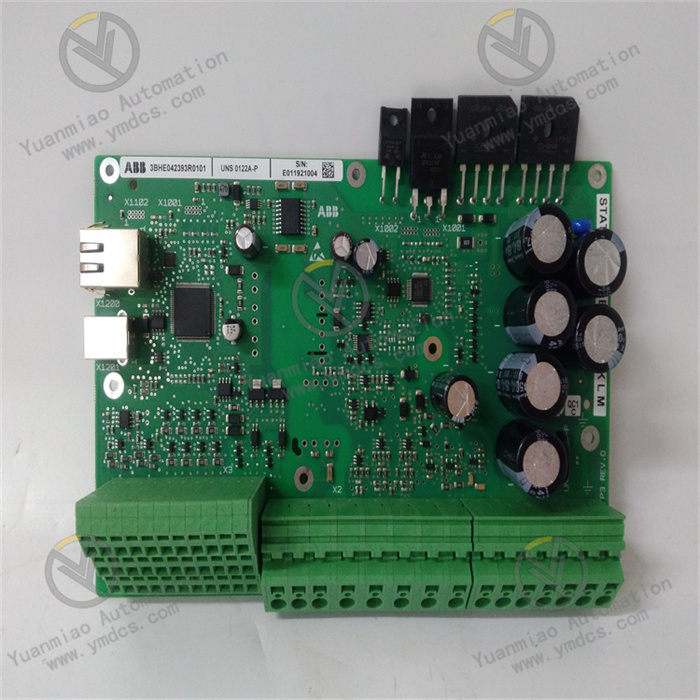
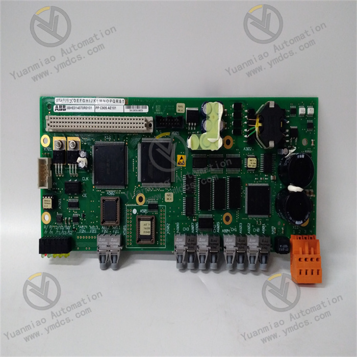
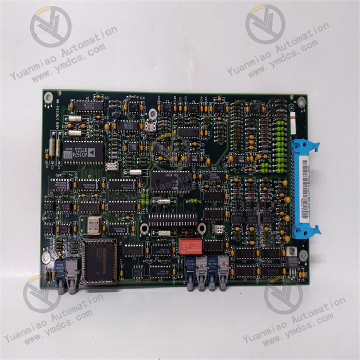
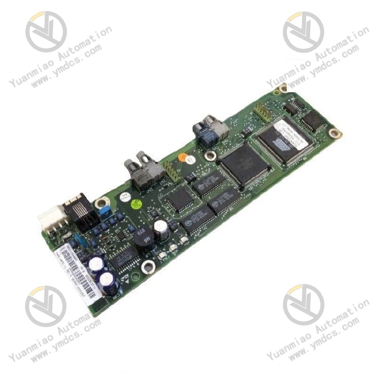
ABB NAMC-11C, part number 3BSE017194R1, is a dedicated main motor control board for ABB ACS600 series high-power frequency converters, serving as the core operation motherboard of the drive system and fully compatible with ACS601/ACS604/ACS607 full-range industrial high-power inverter units. It undertakes all core functions including motor core algorithm operation, logic control, bus interaction and system fault diagnosis.
2. Hardware Structure and Composition
2.1 High-Performance Drive Main Control Operation Unit
A built-in independent 32-bit dedicated drive DSP processor runs the core DTC Direct Torque Control algorithm independently, completes real-time calculation of motor flux, torque and speed without occupying resources of external communication cards. It supports multi-segment speed curves, torque limiting, braking logic and master-slave synchronous linkage operation, and multiple versions of firmware for general transmission, crane and paper making can be loaded and switched freely via upper debugging software. Built-in large-capacity Flash and RAM storage permanently saves motor parameters, fault records and process configurations without data loss after power off.
2.2 Fiber Isolated High-Speed Control Bus Unit
Dual-channel fiber transceiving optical ports are arranged on the board, realizing high-speed real-time control signal interaction with inverter power units and detection boards through optical fibers. Fiber medium completely isolates strong electromagnetic interference from power loops, eliminating harmonic waves and surges generated by high-power inverter modules from backflowing into the main control operation loop. Optical ports integrate optical power detection circuits to automatically trigger fault alarms and upload fault codes upon fiber breakage or optical attenuation.
2.3 Multi-Channel Isolated I/O & Expansion Bus Slot Unit
Integrated isolated digital input/output and analog setpoint feedback acquisition loops can directly access 24V field limit switches, valve feedback and 4~20mA speed setpoint signals. Reserved standard internal expansion slots can be plugged with NDCO-03 multi-protocol gateway cards, encoder feedback cards and pulse counting cards to expand fieldbus communication and high-precision speed collection functions. Transient absorption protection components are integrated into all I/O loops to absorb reverse electromotive force of inductive loads and prevent breakdown of sampling circuits.
2.4 Panel Status Diagnosis LED Indication Unit
Multiple groups of two-color status LEDs are arranged on the side of the board, corresponding to power PWR, DSP operation RUN, fiber bus LINK, hardware fault FAULT and external communication COM respectively. Steady RUN light indicates normal operation of main control algorithms; steady FAULT light signals hardware failure, fiber breakage or program abnormality; flashing COM light represents data transceiving of external buses. All fault codes and fault sequence records can be fully read and traced through DriveWindow debugging software.
2.5 Isolated Power Supply & Multi-Stage Hardware Protection Unit
Power is supplied uniformly by the inverter internal 24VDC auxiliary power supply, with built-in independent isolated power conversion and filtering circuits integrating five levels of hardware protection including overvoltage, undervoltage, reverse polarity, overcurrent and electrostatic surge. The operation loop, fiber bus and external I/O are fully electrically isolated. Short-circuit of single-channel I/O or external bus faults only lock the corresponding channel without interrupting core motor control operation to ensure safe short-term shutdown of equipment.
2.6 Standardized Inverter Built-In Modular Housing Unit
3. Technical Specifications
(1) Main Control Operation & Drive Performance Specifications
(2) Overall Electrical Specifications
(3) Environmental Protection Specifications
(4) Mechanical Installation Specifications
4. Product Functions and Features
Equipped with ABB self-developed DTC Direct Torque Control technology natively, it realizes fast torque response and accurate speed regulation without additional incremental encoders, suitable for high-precision process scenarios such as anti-slipping hook of lifting equipment, constant tension control of rolling mills and multi-motor synchronization of paper machines, with superior control performance compared with traditional V/F and vector control mainboards.
Multiple independent application firmware are built into the board, which can be switched between general transmission, port crane and master-follower synchronous control programs with one click via debugging software. The same model main control board can be used for fans, water pumps, gantry cranes and steel rolling production lines, reducing spare part types and equipment maintenance inventory costs.
Fiber is adopted to transmit internal high-speed control signals, fully isolating high-frequency harmonics, inverter surges and cabinet potential differences generated by power modules, eliminating analog signal drift, speed fluctuation and random communication offline, suitable for high electromagnetic interference field sites such as metallurgy and mines.
Reserved standard expansion slots can be matched with NDCO-03 gateway cards to access third-party PLC and DCS systems via PROFIBUS, Modbus TCP/RTU; encoder cards can be installed to realize full torque closed-loop at zero speed, meeting high-precision tension and positioning control working conditions.
It real-time monitors full-dimensional operating status including fiber links, power supply, I/O channels, DSP operation and motor load. Fault timing, torque-speed curves and fault codes are automatically locked upon fault occurrence and uploaded to the upper monitoring system. Maintenance staff can quickly locate hardware, line and process abnormalities, greatly shortening downtime maintenance duration.
Unified board size, plug-in interface and power supply definitions allow direct in-situ replacement of aging damaged main control boards of ACS600 series inverters without modifying inverter power loops and external wiring. Operation can be restored only by re-downloading motor parameters and process configurations with short equipment shutdown renovation time.
5. Applicable Working Conditions and Application Scenarios