Description
1. Overview
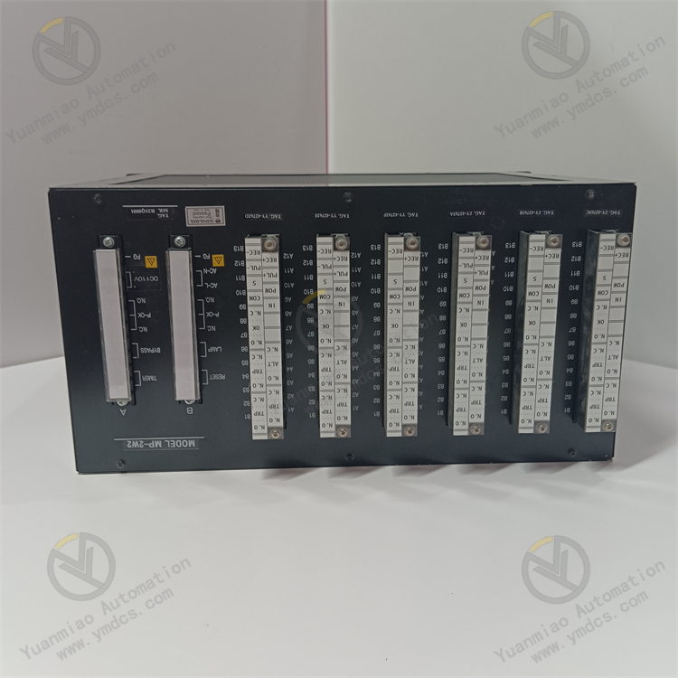
SHINKAWA VM-5P3 is a dedicated phase mark (keyphasor) processing unit for the VM-5 series TSI (Turbine Supervisory Instrumentation) system developed by Shinkawa Electric Japan. Designed in strict accordance with API 670, the international standard for rotating machinery monitoring, it serves as a core timing reference supporting module for the complete rack-mounted TSI system. It can only be installed on the backplane of standard instrument racks VM-5H3 and VM-5W1, and is incompatible with the standalone VM-5G rack.
This module supports synchronous input of two keyphasor signals. It connects with eddy current probes and magnetoelectric tachometer sensors to collect one-per-revolution zero-reference pulses from the rotating shaft, and performs waveform shaping, threshold trigger level setting and pulse buffered transmission output. It supplies synchronous reference signals essential for rotational speed acquisition, phase positioning, orbit plotting, Bode diagram analysis and field balancing correction to vibration monitoring modules within the same rack.In addition, it features power supply self-check for the rack system, diagnostic detection of abnormal keyphasor input, and output of system general OK relay contact signals. Fault information can be uploaded to the upper TSI host system and recorded in the SOE (Sequence of Events) timestamp log.
2. Technical Features
Independent Dual-Channel Keyphasor Acquisition & Precise Shaping of Reference Signals
Equipped with two fully isolated keyphasor input channels with an input impedance of approximately 10 kΩ, it accepts raw pulse signals within a wide voltage range of 0~25 VDC. Users can customize trigger levels and hysteresis thresholds via DIP switches on the front panel to filter spurious false trigger pulses caused by shaft burrs and electromagnetic interference.A dedicated internal waveform shaping circuit regularizes pulse edges to eliminate rotational speed fluctuation and phase offset induced by signal jitter, ensuring a stable and reliable single reference pulse per shaft revolution.
Dual-Channel Signal Transmission Output for Simultaneous Data Acquisition by Multiple Systems
- Buffered output: voltage range -1~-20 VDC, output impedance 50 Ω;
Pulse output with two level options (PL: -1~+1 V, PH: 4~6 V), also with 50 Ω low-impedance drive.It enables parallel reading of keyphasor and rotational speed signals by local TSI monitoring cards, DCS systems, fault diagnosis analyzers and portable data loggers simultaneously without mutual load interference.
System-Level Full Self-Diagnosis & Closed-Loop Fault Alarm
The module continuously monitors the backplane supply voltage of the rack, continuity of the two keyphasor input loops and signal overrange status. In case of abnormal power supply, probe open circuit, signal loss or pulse anomalies, it locks the output state of the system OK relay with configurable normally open / normally closed and energized / de-energized excitation modes.Two alarm reset modes (automatic reset and latching manual reset) are selectable. Fault signals will not interfere reversely with the rack backplane bus and other monitoring modules, facilitating quick on-site troubleshooting of reference measuring point faults.
Native Rack Compatibility & Rapid Deployment Without Extra Configuration
Adopting the unified single-slot plug-in structure of the VM-5 series, it draws power and communicates directly after being inserted into the backplane of VM-5H3 / VM-5W1 racks with no need for separate external power and communication wiring.No reconfiguration of original TSI measuring point logic and alarm parameters is required. Vibration, eccentricity and differential expansion modules in the same rack can automatically identify the phase reference signal output by this unit, allowing immediate commissioning for new system integration and expansion & retrofitting of legacy units.
Industrial Triple-Proof Rugged Structure with Multiple Certifications for Harsh Environments
3. Specification Parameters
3.1 Basic Model Parameters
- Model No.: VM-5P3
- Brand & Series: SHINKAWA VM-5 Series Dedicated Phase Reference Module for TSI Systems
- Module Type: Dual-Channel Keyphasor / Phase Mark Signal Processing Unit
- Core Functions: Dual-channel keyphasor pulse acquisition, waveform shaping, level threshold configuration, buffered signal output, standard tachometer pulse transmission, rack power self-check, input fault alarm, system general status contact output
- Compatible Racks: Only VM-5H3 and VM-5W1 instrument racks; not applicable to VM-5G standalone racks
- Compatible Front-End Sensors: SHINKAWA FK series eddy current displacement probes, magnetoelectric tachometer sensors, general proximity keyphasor probes
- Compatible Back-End Modules: Full range of VM-5 monitoring cards including VM-5Y1, VM-5K, VM-5N, VM-5S
- Applicable Equipment: Turbo-generator sets, gas turbines, large centrifugal compressors, blowers, offshore platform compressors, marine power rotating units
3.2 Signal Acquisition & Output Parameters
- Input Channels: 2 independent keyphasor signal inputs
- Input Impedance: 10 kΩ, input voltage range 0~25 VDC
- Trigger Configuration: Four selectable hysteresis thresholds via front panel DIP switches: 0.1 V / 0.2 V / 0.5 V / 1.0 V
- Buffered Output: 2-channel voltage buffered output, output impedance 50 Ω, output amplitude -1~-20 VDC
- Pulse Output: 1 channel of shaped standard pulse output, impedance 50 Ω; PL level: -1~+1 V, PH level: 4~6 V
- Signal Performance: Regular pulse edges, ultra-low temperature & time drift, no phase shift or rotational speed counting jump during long-term operation
3.3 Electrical & Alarm Parameters
- Power Supply: Unified 24 VDC power fed from VM-5 rack backplane; no independent external power port
- Alarm Contacts: Passive system OK relay contacts with four wiring modes: NO/NC, energized/de-energized
- Reset Modes: Switchable via front panel between automatic reset and fault latching manual reset
- Built-in Protection: Input overvoltage clamping, output short-circuit current limiting, reverse polarity anti-damage protection, surge voltage suppression
- Communication Linkage: Fault events uploaded via rack system bus and recorded in system SOE timestamp logs
3.4 Environmental Parameters
- Operating Temperature: Standard version -10 ℃ ~ +60 ℃; wide-temperature industrial version -40 ℃ ~ +70 ℃
- Storage Temperature: -55 ℃ ~ +125 ℃
- Operating Humidity: 5% ~ 95% RH (non-condensing); marine / tropical versions with enhanced moisture and condensation resistance
- Protection Structure: Plug-in fully sealed modular structure with dust, moisture and vibration resistance
- Operation Mode: 24-hour non-stop continuous stable monitoring
3.5 Mechanical & Maintenance Parameters
- Mounting Method: Standard single-slot embedded plug-in rack installation, tool-free disassembly
- Structural Features: Highly integrated PCB design with shock & impact resistance and low aging rate
- Status Indication: Front panel LED indicators for power normal, Channel 1 input fault, Channel 2 input fault and system alarm respectively
- Configuration Adaptation: No separate programming required; modules within the same rack automatically recognize and link with the reference signal
- Maintenance Instructions: Replacement allowed only after rack power cut; hot swapping under power is strictly forbidden. Retrofit on legacy systems only requires power-off of the target slot instead of the whole rack.
4. Working Principle
- Output as buffered voltage signals directly to vibration and eccentricity monitoring modules in the same rack to serve as phase synchronization reference;
Converted into standard amplitude pulses for external transmission to DCS and fault diagnosis systems for rotational speed and phase sequence reading.
5. Application Scenarios
Establishment of Reference Signals for TSI Systems of Power Plant Turbine Units
This module is standard equipment in TSI cabinets of thermal power and combined-cycle power plant steam turbines. It collects keyphasor pulses from the main shaft and provides phase reference for shaft vibration monitoring modules to support vibration analysis during unit startup & shutdown, rotor unbalance fault diagnosis and on-site dynamic balancing. Rotational speed signals are transmitted remotely to DCS for rotational speed interlock protection logic.
Rotor Dynamic Condition Monitoring for Large Compressor Units
For large centrifugal compressors in petrochemical and coal chemical industries, the keyphasor signal from this module enables orbit plotting, which accurately identifies hidden faults including rotor-stator rubbing, misalignment and oil whirl. It compensates for the limitation that amplitude-only vibration monitoring cannot locate fault types.
Function Upgrade and Capacity Expansion of Legacy VM-5 Systems
The module can be directly plugged into vacant slots of existing VM-5H3 / VM-5W1 racks without modifying original sensor wiring and system configuration to add phase analysis and remote tachometer output functions. Installation can be completed during unit overhaul with short construction period and minimal downtime loss.
Monitoring for Offshore Platform and Marine Power Equipment
The classification society certified version is adopted to adapt to offshore environments with salt spray corrosion and hull vibration. It is used for reference signal acquisition in TSI systems of offshore gas turbines and platform compressors, complying with marine equipment safety standards and meeting requirements of long-term offshore unattended operation.
Signal Connection for Predictive Maintenance & Diagnosis Platforms