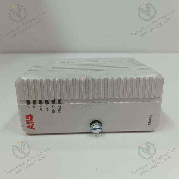
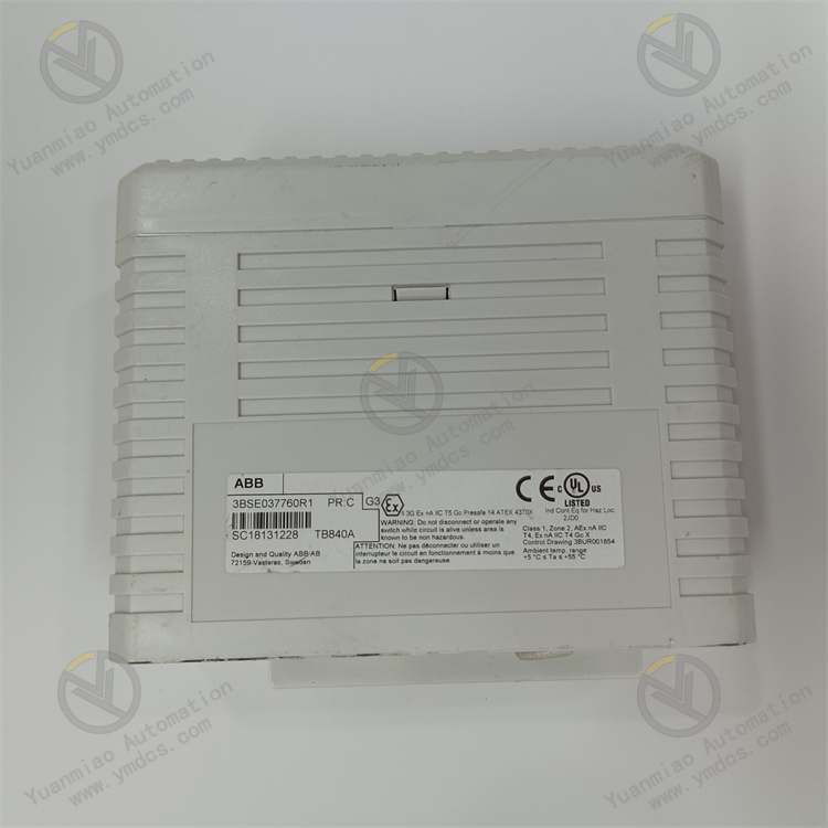
Description
1. Product Overview
Model: TB840A
Part Number: 3BSE037760R1
Brand: ABB
Product Name: ModuleBus Optical‑Fiber Cluster Redundant Modem / Bus Redundancy Interface Module
Product Positioning
The TB840A is a dedicated core redundant communication module for ABB System 800xA control system and S800 I/O distributed system. It serves as a critical hardware unit for opto‑electric conversion and redundant networking of I/O bus in industrial DCS systems. It undertakes key tasks including data conversion between electrical ModuleBus and optical‑fiber ModuleBus, link redundancy backup and bus condition monitoring. It provides highly‑reliable communication link support for the complete I/O sub‑station, and acts as a key supporting spare part to guarantee non‑stop and bumpless operation of industrial automation systems.
Core Functions
It realizes bidirectional transparent data transmission and opto‑electric isolation conversion between electrical bus and optical‑fiber bus. It supports dual‑optical‑fiber‑bus redundant architecture and achieves millisecond‑level bumpless switchover upon single fiber‑link fault, line interference or port abnormality, so as to avoid I/O data loss, system offline and equipment mis‑operation caused by bus communication interruption. It monitors bus power supply status, link communication quality and module operating conditions in real‑time, and uploads status information to the master control system. It ensures stable, real‑time and reliable data transmission of DCS I/O sub‑stations and supports continuous production of critical processes such as chemical, power and metallurgical industries.
Applicable Systems
ABB System 800xA automation control system, full‑range S800 I/O distributed input‑output system, AC800M / AC800PEC controllers. Compatible with TU840, TU841 redundant bases and complete ABB bus networking architecture.
Application Scenarios
Widely used in thermal power plants, hydropower plants, petrochemical plants, metallurgy & mining, rail transit and large‑scale industrial automatic production lines. Designed for redundant DCS control systems requiring high‑reliability non‑stop production. Suitable for installation in central control cabinets, remote I/O cabinets and field sub‑stations, meeting the requirement of 7×24‑hour continuous stable operation in industrial sites.
2. Technical Features
Dual‑Fiber Redundant Bus Architecture for Zero‑Communication‑InterruptionEquipped with two independent ModuleBus optical‑fiber communication ports for parallel dual‑link redundant operation. The module connects two separate optical‑fiber buses while sharing one electrical bus. When one link suffers failure, cable breakage or interference distortion, the system automatically switches to the standby link seamlessly without data loss or system disturbance. It eliminates single‑point‑failure risks of single‑link communication and greatly improves the reliability of DCS bus.
Opto‑Electric Isolation Conversion with Superior Anti‑Interference PerformanceComplete opto‑electric isolation between electrical bus and optical‑fiber bus blocks cross‑link transmission of interference signals such as high‑voltage pulses, converter harmonics, electromagnetic radiation and ground loop current in industrial sites. Optical‑fiber transmission without electrical contact avoids circuit crosstalk and electric leakage. It perfectly adapts to harsh industrial conditions with strong electromagnetic interference and guarantees accurate and stable I/O signal transmission.
Real‑Time Bus Condition Monitoring and Self‑DiagnosisComprehensive hardware self‑diagnosis and bus monitoring functions identify optical‑fiber link abnormality, bus signal attenuation, port fault, power supply anomaly and data packet loss in real‑time. Fault alarm codes and status information are uploaded actively. Accurate fault location is supported without section‑by‑section line inspection, which greatly shortens maintenance time.
Low‑Power Industrial‑Grade Stable DesignAdopts dedicated low‑power main‑control chip with low power consumption and low heat generation, no performance degradation under long‑term continuous operation. Built‑in industrial filter circuits and voltage‑stabilizing protection loops offer strong adaptability to power‑supply fluctuation. It is dust‑proof, moisture‑proof, temperature‑resistant and anti‑aging for long‑term non‑stop cabinet‑mounted operation.
Native ABB‑System CompatibilityCustom‑developed for ABB System 800xA and S800 I/O systems. Bus protocol, data frame format, communication timing and hardware interfaces are fully original‑factory‑matched. No program rewriting or parameter adaptation is required. Direct in‑situ replacement of old modules is available for legacy‑system retrofitting, spare‑part replacement and new‑project complete‑set supporting.
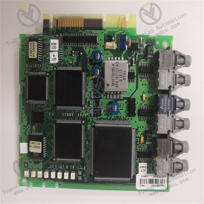
Modular Plug‑in Structure for Convenient MaintenanceStandard plug‑in modular design with dedicated redundant base enables easy disassembly and firm fixation. Hot‑swap replacement is supported without system shutdown. On‑board status LED indicators intuitively display operation, communication, fault and link status for rapid condition judgment and reduced system‑shutdown risks.
- Independent Bus Power‑Supply Protection for High SafetyBuilt‑in I/O bus isolated power‑supply protection mechanism provides stable isolated power for downstream I/O modules. It effectively prevents downstream I/O module damage and signal disorder caused by upstream power‑supply anomaly or voltage fluctuation. Multi‑layer protections including over‑voltage, over‑current and short‑circuit are implemented to ensure safe operation of the whole I/O sub‑station.
3. Specification Parameters
| Item | Parameter |
|---|---|
| Model | TB840A |
| Part Number | 3BSE037760R1 |
| Device Type | ModuleBus Optical‑Fiber Redundant Modem / Bus Interface Module |
| Applicable Systems | ABB System 800xA, S800 I/O Distributed System, AC800M / AC800PEC Controllers |
| Core Functions | Opto‑electric bus conversion, dual‑fiber‑link redundancy, bus condition monitoring, I/O bus isolated power supply, fault self‑diagnosis, transparent data transmission |
| Communication Ports | Dual ModuleBus optical‑fiber ports, single ModuleBus electrical port |
| Power Supply | Base‑mounted bus power supply, DC24V industrial regulated power supply |
| Total Power Consumption | ≤5W (low‑power design) |
| Operating Temperature | -20℃~+70℃ |
| Storage Temperature | -40℃~+85℃ |
| Ambient Humidity | 5%~95%, non‑condensing |
| Protection Features | Opto‑electric isolation, surge suppression, short‑circuit protection, over‑voltage & over‑current protection, EMC electromagnetic compatibility |
| Operation Modes | Dual‑link hot‑standby redundancy, automatic bumpless switchover, single‑link independent operation |
| Compatible Base | TU840, TU841 dedicated redundant mounting base |
| Mounting Method | Standard cabinet card‑mounting, base‑fixed installation |
| Applicable Equipment | Full‑range S800‑series I/O modules, complete ABB DCS controllers |
| Origin | Original imported from Switzerland |
| Product Characteristics | Dual‑fiber redundancy, opto‑electric isolation & anti‑interference, low power consumption, self‑diagnosis & alarm, full original‑factory compatibility, hot‑swappable, high operational redundancy |
4. Working Principle
Power‑On Initialization and Hardware Self‑TestAfter power‑on, the module automatically completes initialization, sequentially performing hardware‑circuit self‑test, optical‑fiber port detection, electrical bus matching, power‑supply‑condition verification and communication‑protocol loading. It comprehensively checks link faults, hardware anomalies and configuration issues. Upon passing self‑test, it enters normal redundant operation mode, completes bus handshaking with master controllers and downstream I/O modules, and lays a solid foundation for system data transmission.
Bidirectional Opto‑Electric Data Conversion and Transparent TransmissionAs the transit core between electrical ModuleBus and optical‑fiber ModuleBus, the module implements bidirectional opto‑electric conversion. Control commands issued by controllers as well as field analog and digital signals collected by downstream I/O modules are losslessly converted between electrical and optical signals for cross‑bus transparent transmission, ensuring distortion‑free, low‑latency and loss‑free data transmission.
Dual‑Link Parallel Monitoring and Automatic SwitchoverDuring operation, communication quality, signal strength and data‑transmission status of two optical‑fiber links are monitored continuously in real‑time. The two links work in parallel as mutual hot‑standby. In case of cable breakage, signal attenuation, interference distortion or port fault on any link, the module triggers redundant‑switchover logic within milliseconds and takes over all data transmission via the healthy link. System communication remains uninterrupted without impact on equipment status, realizing bumpless fault‑tolerant operation.
Bus Power‑Supply and Safety Protection ManagementThe built‑in isolated voltage‑stabilizing power‑supply circuit provides safe and stable bus power for the entire downstream I/O sub‑station. It monitors supply voltage and load current in real‑time. Once over‑voltage, over‑current or short‑circuit occurs, current‑limiting and power‑cut‑off protection are activated immediately to isolate faulty loops and prevent whole‑set I/O module damage and system paralysis caused by single‑point‑fault propagation.
- Status Self‑Diagnosis and Fault Traceability UploadThe module continuously records module operating status, bus communication conditions and link abnormality information. It accurately identifies link faults, hardware failures and power‑supply anomalies, generates fault codes and uploads them to DCS background system, and triggers local and remote alarms. Operation‑maintenance personnel can quickly locate fault points and eliminate hidden dangers for fast system recovery.
5. Common Faults and Troubleshooting
Phenomenon: No operation indicator after module power‑on; system fails to recognize the bus modulePossible Causes
① Abnormal base bus power supply, insufficient or lost DC24V voltage;
② Poor contact between module and base, oxidized and dust‑covered gold‑finger contacts;
③ Damaged base hardware or faulty bus circuit;
④ Damaged internal power‑supply chip or abnormal firmware.
Troubleshooting
Power off the system and allow sufficient discharge. Measure cabinet bus supply voltage and circuit continuity, inspect power breakers and wiring. Extract the module, clean gold‑finger contacts and base‑slot dust, then re‑insert and fix firmly. Inspect base wiring and working status and replace faulty base. If no response persists with normal power supply and contact, hardware failure of the module is confirmed; replace with original spare part.
Phenomenon: Single optical‑fiber link alarm, abnormal communication‑signal attenuationPossible Causes
① Excessive signal loss caused by dirty, worn or offset optical‑fiber ferrule;
② Excessive bending, damage or over‑length of optical‑fiber cable;
③ Aging optical‑fiber port with reduced receiving sensitivity;
④ Link electromagnetic interference or abnormal optical path.
Troubleshooting
Clean optical‑fiber connectors with dedicated fiber‑optic cleaning tools, check connector integrity and re‑plug and fasten fibers. Route cables properly to avoid excessive bending or squeezing; replace damaged fibers. Measure optical‑path signal loss and optimize wiring if threshold is exceeded. Clean and calibrate module optical‑fiber ports. If alarms persist, port failure is confirmed; replace the module.
Phenomenon: Frequent dual‑link switchover, unstable bus communication and data jitterPossible Causes
① Large signal‑quality difference between two optical‑fiber links and unstable single link;
② Bus‑supply‑voltage fluctuation and severe ripple interference;
③ Data‑transmission distortion induced by strong on‑site electromagnetic interference;
④ Abnormal module communication logic or disordered firmware.
Troubleshooting
Measure signal quality of both optical‑fiber links respectively and repair weak‑link faults. Optimize cabinet power‑supply system and install filters for voltage stabilization. Improve shielding and grounding of cabinet and cables to eliminate electromagnetic interference. Reboot the module for program reset and re‑flash original‑factory firmware. If faults remain, module performance degradation is confirmed; replace spare part.
Phenomenon: Frequent offline status of downstream I/O modules, data packet loss and communication interruptionPossible Causes
① Degraded accuracy of module opto‑electric conversion circuit and abnormal data forwarding;
② Mismatched bus impedance and disordered networking parameters;
③ Abnormal module load and insufficient power‑supply load capacity;
④ Reduced communication stability due to module hardware aging.
Troubleshooting
Verify bus networking parameters and impedance configuration and correct parameter deviations. Check module loaded power‑supply status and troubleshoot downstream I/O short‑circuit or overload faults. Optimize bus networking architecture to avoid signal conflict. If abnormalities persist after circuit and parameter inspection, module failure is confirmed; replace with original module.
Phenomenon: High module operating temperature, frequent crash and restart, unstable operationPossible Causes
① Blocked cabinet air duct, heavy dust accumulation and poor heat dissipation;
② Abnormal power consumption of aged internal components under long‑term high‑load data forwarding;
③ Excessively high bus‑supply voltage and abnormal power supply;
④ Stuck or abnormal firmware.
Troubleshooting
Thoroughly clean cabinet air ducts and module surface dust, improve ventilation & heat dissipation and control cabinet ambient temperature. Measure and calibrate bus supply voltage to eliminate power anomalies. Re‑flash stable original‑factory firmware. If faults recur continuously, module aging failure is confirmed; replace spare part in advance to avoid system‑shutdown risks.
Phenomenon: Redundant switchover failure; system communication interruption upon single‑link faultPossible Causes
① Redundancy function disabled or incorrect configuration parameters;
② Inconsistent dual‑link parameters and mismatched port operation modes;
③ Damaged hardware for redundant‑switchover logic or abnormal firmware.
Troubleshooting
Access DCS background to verify module redundancy configuration, enable dual‑link hot‑standby function and unify operating parameters of both ports. Re‑configure redundant‑switchover logic and test switchover performance by simulating link faults. If switchover still fails with correct parameters, hardware failure is confirmed; replace the module immediately to guarantee system redundancy safety.