Description
1. Overview
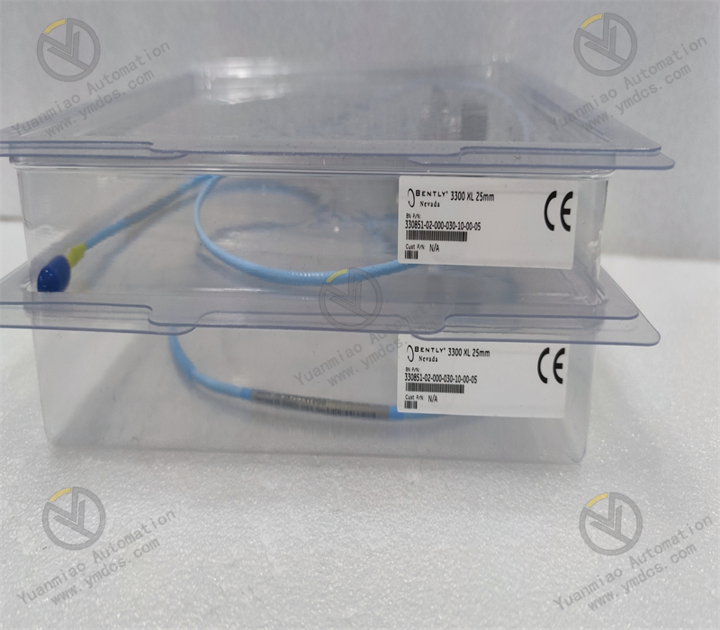
Bently Nevada 330851‑02‑000‑030‑10‑00‑05 is a high‑precision eddy‑current displacement probe of the Baker Hughes Bently Nevada 3300 XL 25 mm series. It is a non‑contact condition‑monitoring sensor dedicated for large heavy‑duty rotating machinery and serves as the core sensing element of Bently Nevada’s 25 mm extra‑range eddy‑current monitoring system. Designed for critical main equipment such as steam turbines, large centrifugal compressors, gas expanders, blowers and heavy‑duty pumps, it monitors key parameters including shaft vibration, shaft displacement, shaft eccentricity, casing differential expansion and rotor axial thrust for large‑shaft‑diameter units. It is well‑suited for heavy‑duty operating conditions featuring large displacement and large installation gaps.
This probe adopts an integrated stainless‑steel hermetically‑sealed construction and performs non‑contact dynamic measurement based on high‑frequency eddy‑current induction principle. Compared with conventional 8 mm and 11 mm probes, it delivers outstanding advantages including extra measurement range, large allowable installation gap and superior environmental adaptability for heavy‑duty units with large shaft diameters, high vibration amplitudes and considerable axial thrust. Natively compatible with the full range of Bently Nevada 3500, 1900 and 1701 monitoring systems, it forms a complete 25 mm eddy‑current monitoring chain when paired with 330850‑series proximitors and 330730‑series extension cables. Widely deployed in thermal‑power, oil‑gas, chemical and metallurgical heavy industries, it acts as a core sensing device for refined condition‑based monitoring, fault early‑warning and intelligent‑maintenance retrofits of heavy‑duty machinery.
2. Functions and Features
2.1 Core Functions
25 mm Extra‑range Non‑contact Displacement Monitoring: Dedicated 25 mm measurement range for heavy‑duty units with large shaft diameters, high vibration amplitudes and heavy axial thrust. It accurately captures dynamic parameters such as radial shaft vibration, axial displacement, eccentricity and differential expansion, and overcomes common drawbacks of small‑range probes including insufficient measuring range and frequent over‑range alarms.
High‑precision Dynamic Condition Acquisition: Working on high‑frequency eddy‑current induction principle with zero mechanical contact and zero wear. It continuously captures tiny displacement fluctuations and dynamic vibration variations, enabling reliable identification of typical heavy‑machinery faults such as rotor unbalance, misalignment, shaft bending, oil‑film oscillation and rotor‑stator rub‑impact.
Full‑system Standardized Compatibility: Fully compliant with electrical specifications of the 3300 XL 25 mm system. Compatible with all rack‑mounted and modular Bently Nevada monitoring systems. Plug‑and‑play with genuine proximitors and extension cables without complex parameter configuration.
Fault‑tolerant Monitoring with Wide Installation‑gap Margin: Offers large allowable initial installation gap for scenarios with confined mounting space, significant shaft‑system deformation and substantial thermal expansion. It effectively prevents probe rubbing, measurement over‑range and installation interference.
24/7 On‑line Machinery Condition Monitoring: Supports 7×24‑hour continuous operation under harsh conditions including high temperature, vibration, oil contamination, dust and heavy electromagnetic interference. It outputs high‑fidelity raw measurement data for fault prediction and condition‑based maintenance.
Full‑chain Fault‑diagnosis Support: Cooperates with proximitors and monitoring hardware to detect loop open‑circuit, short‑circuit, signal anomaly and parameter drift. It mitigates invalid readings, false alarms and missed alarms to ensure safety and reliability of monitoring chains for heavy‑duty units.
2.2 Product Characteristics
Extra Range and High Measurement Accuracy: 25 mm dedicated measuring range with excellent linearity and high resolution. It performs accurate measurement under large‑displacement conditions without distortion or offset across full range to satisfy precision fault‑diagnosis requirements for large‑scale machinery.
M30×2 Standard Threaded Mounting: Code 02 corresponds to M30×2 standard mounting thread for high universality and firm fastening. It fits standard mounting bases of heavy‑duty‑unit measuring points and facilitates fast field installation, replacement and calibration.
Broad‑temperature Industrial Performance: High‑temperature‑resistant sensing construction with ultra‑low temperature drift. Measurement readings remain stable without zero‑point shift or accuracy degradation under temperature cycling and unit thermal‑expansion conditions.
High‑strength Sealed Explosion‑resistant Construction: One‑piece hermetically‑sealed stainless‑steel enclosure providing dust‑proof, oil‑proof, moisture‑proof and corrosion‑proof performance. Suitable for hazardous and heavily‑polluted sites in chemical and oil‑gas industries with high shock‑resistance and vibration‑fatigue resistance.
Stable Signal with Strong Anti‑interference Capability: Optimized high‑frequency induction and signal‑output architecture. When used with matched shielded cables, it effectively suppresses electromagnetic disturbances from variable‑frequency drives, high‑voltage apparatus and power cables for clean, jitter‑free and undistorted signals.
Long‑term Operation with Low Maintenance Cost: Built with premium components and precision manufacturing. Stable performance during prolonged continuous operation with minimal faults and infrequent recalibration requirements, lowering maintenance and spare‑part expenses for heavy‑duty‑unit measuring points.
3. Specifications
| Item | Specifications |
|---|---|
| Model | 330851‑02‑000‑030‑10‑00‑05 |
| Product Type | 3300 XL 25 mm Eddy‑current Displacement Probe |
| Brand & Manufacturer | Bently Nevada (Baker Hughes) |
| Measuring Principle | High‑frequency non‑contact eddy‑current induction |
| Rated Measuring Range | 25 mm |
| Mounting Thread | M30×2 (Code 02 standard thread) |
| Effective Probe Length | 30 mm (Code 030) |
| Integral Cable Length | 10 m (Code 10) |
| System Compatibility | 3300 XL 25 mm system; compatible with 330850 proximitor, 330730 extension cable, 3500 / 1900 monitoring systems |
| Linearity Accuracy | ±1.5% Full‑Scale |
| Recommended Initial Installation Gap | 8‑12 mm |
| Operating Temperature (Probe Tip) | ‑51 ℃ ~ +177 ℃ |
| Operating Temperature (Cable Section) | ‑40 ℃ ~ +121 ℃ |
| Storage Temperature | ‑51 ℃ ~ +185 ℃ |
| Ambient Humidity | 5%‑95% RH, non‑condensing |
| Housing Material | Industrial stainless‑steel hermetically‑sealed explosion‑resistant enclosure |
| Performance Features | Extra measuring range, high accuracy, low temperature drift, strong anti‑interference, non‑contact & wear‑free, wide‑temperature stability, for heavy‑duty machinery |
4. Operating Principle
The Bently Nevada 330851‑02‑000‑030‑10‑00‑05 probe operates on the high‑frequency non‑contact eddy‑current induction principle. As the core sensing unit of the 25 mm extra‑range monitoring system, it acquires precise and stable shaft‑system parameters especially for heavy‑duty rotating machinery under large‑displacement and large‑gap conditions.
During operation, the built‑in high‑frequency induction coil generates a stable alternating electromagnetic field. The field penetrates the metallic shaft surface and induces eddy currents within the near‑surface layer of the rotor. When radial vibration, axial displacement, eccentricity or other dynamic movements occur on the rotor, the gap between probe tip and shaft surface varies accordingly, which brings linear changes in eddy‑current intensity and coil impedance.
Weak electrical signals corresponding to gap variations are transmitted via the integrated shielded cable to the dedicated 330850‑series proximitor. The proximitor executes filtering, noise reduction, amplification, linear calibration and temperature compensation to eliminate measurement errors caused by thermal drift, electromagnetic interference and line loss. It converts physical gap values into standard linear voltage outputs. Processed signals are sent to downstream 3500 / 1900 monitor modules for real‑time display, trend logging, spectrum analysis and over‑limit alarming of shaft vibration, shaft displacement, differential expansion and eccentricity.
Equipped with proprietary extra‑range linear algorithm and wide‑temperature compensation mechanism, this 25 mm probe maintains full‑range linear measurement without signal saturation or distortion under large‑gap and large‑displacement fluctuations, which differentiates it from small‑range probes. Combined with genuine sealing and shielding technologies, it withstands high temperature, vibration and oil contamination in field environments and guarantees authenticity, continuity and stability of monitoring data for heavy‑duty units.
5. Application Scenarios
Core‑parameter Monitoring for Heavy‑duty‑unit Shaft Systems: For critical main equipment including large steam turbines, centrifugal compressors, flue‑gas expanders, large blowers and heavy‑duty pumps with large shaft diameters and heavy axial thrust. It measures shaft vibration, axial displacement, shaft eccentricity and casing differential expansion.
Special‑purpose Monitoring for Large‑displacement Conditions: Leverages the 25 mm extra range to avoid over‑range measurement, data distortion and frequent false alarms during unit start‑up / shutdown, load variation and thermal expansion with large axial thrust and high vibration amplitudes.
Long‑term Monitoring under Severe Heavy‑industry Conditions: High temperature resistance, oil resistance, strong anti‑interference and high stability enable reliable deployment in harsh on‑machine environments of thermal‑power, chemical, oil‑gas and metallurgical plants featuring high temperature, dust, heavy EMI and drastic operating‑condition fluctuations.
Retrofit of Legacy Heavy‑duty Measuring Points: Replaces aged small‑range probes and degraded measuring points to resolve pain points such as insufficient range, excessive thermal drift, poor anti‑interference performance and frequent false alarms, and improves shaft‑system monitoring accuracy and fault‑diagnosis capability for large‑scale machinery.
Accurate Fault Prediction and Diagnosis for Machinery: Continuously collects shaft‑system displacement and vibration trend data to identify typical faults including rotor misalignment, shaft bending, rub‑impact, oil‑film oscillation and foundation loosening, supporting predictive maintenance and hazard mitigation.
New‑unit Matching and System Expansion for Large‑scale Machinery: Suited for new‑build heavy‑industry monitoring systems, legacy‑system point expansion and technical‑retrofit point relocation. Standard factory‑defined parameters ensure compatibility and reduce commissioning workload without full‑system recalibration.
6. Common Faults and Troubleshooting
6.1 Readings stay constant without dynamic fluctuation
Root Causes: Aged probe induction coil with degraded sensitivity; oil, dust and scale deposits on probe tip causing electromagnetic‑field failure; open‑circuit / intermittent connection or loose connectors; data‑locking anomaly on proximitor or downstream channels.
Solutions: Clean oil and scale deposits from probe tip to restore normal electromagnetic‑field emission. Inspect probe mounting for looseness and offset. Check cable continuity and connector tightness. Release data lock on host system to resume acquisition. Replace probe if readings remain static after eliminating external faults, indicating hardware failure.
6.2 Data jitter, drift and unstable fluctuation
Root Causes: Improper installation gap outside linear range; severe on‑site EMI and non‑standard shield‑grounding; additional vibration induced by loose probe mounting; damaged cable shielding and abnormal signal attenuation.
Solutions: Readjust installation gap to standard linear interval. Implement single‑end shield grounding and route cables away from power and variable‑frequency high‑voltage equipment. Tighten probe thread to eliminate mounting looseness and induced resonance. Replace damaged or aged cables. Change probe if jitter and drift persist.
6.3 Out‑of‑tolerance accuracy, degraded linearity and incorrect range
Root Causes: Excessive thermal drift from long‑term high‑temperature operation; performance degradation of induction coil; abnormal metal material or foreign‑object interference on target surface; mismatch between system‑range configuration and probe specification.
Solutions: Verify 25 mm‑range system configuration against factory specifications. Clean foreign substances from mounting base and shaft surface to remove metallic interference. Re‑calibrate probe linearity and gap voltage. Install genuine replacement probe if accuracy cannot be recovered and severe linear distortion exists.
6.4 System sensor‑fault and channel‑error alarms
Root Causes: Burnt‑out internal coil or damaged probe circuitry; cable conductor breakage, short‑circuit or insulation failure; oxidized / damp connectors leading to ground short‑circuit; incorrect proximitor parameter setup.
Solutions: Power off and test cable continuity, insulation resistance and resistance‑to‑ground for line‑fault localization. Clean and apply moisture‑proof sealing to connectors. Confirm proximitor parameters match 25 mm‑system requirements. Replace probe for irreparable hardware damage.
6.5 Intermittent signal dropout and sporadic data loss
Root Causes: Probe thread loosening and cable displacement caused by sustained unit vibration; intermittent internal contact from cable bending fatigue; unstable contact resistance due to moisture ingress via failed connector sealing.
Solutions: Retighten probe thread and apply anti‑loosening measures. Optimize cable routing to remove sharp bends and tensile stress. Clean and seal connectors to improve insulation and contact quality. Replace probe and cable assembly if intermittent faults recur.
6.6 Abnormal initial gap‑voltage and calibration failure
Root Causes: Damaged probe tip and failed induction coil; installation gap too large or too small beyond valid linear range; shaft‑surface corrosion or over‑thick coating distorting electromagnetic field; mismatched cable electrical parameters.
Solutions: Adjust installation gap to recommended range. Remove corrosion and thick coatings from rotor surface. Check compatibility of cable and proximitor. Replace spare probe if gap‑voltage remains abnormal indicating probe‑body failure.